Jolla and SailfishOS
Companion Attach/Detach interrupt
Finally first experimental results.
For the CompanionTOH concept to work, I need a way to signal the Jolla:
- A Companion got attached
- A Companion got detached
The external interface of the phone provides us with one Interrupt line, that is low active.
So the task is:
- Drive low Jolla's INT line
- For a reasonable amount of time, for the driver software on the phone to register an interrupt request
- Whenever a Companion is attached
- Whenever a Companion is detached
Circuits
I been playing around with two different kind of circuits:
- one using only cheap and simple discrete parts, like NPN transistors
- one using a little more sophisticated, but still affordable Operational Amplifiers (OPAs)
Both circuits have voltage compare units at there heart. We use them to compare an input voltage with a set threshold voltage and drive the (+) output line high, if the input voltage is above the threshold and the (-) output high, if the input voltage is below the threshold.
Each output line has a capacitor, that will allow a following driver transistor to pull the interrupt line low for a limited amount of time only, when this output line is activated by an according state change on the input line.
The time depends on the capacity of this capacitor. Once the capacitor is loaded the interrupt line goes back to high.
For now the values are chosen arbitrary, since it is yet unknown if the interrupt line of the Jolla is a real interrupt line (meaning the MCU will call the Interrupt Service Routine [ISR] kind of right away) or if is a general purpose input line that has to be polled by the software (meaning there is a delay). For the first case a short signal is good. In the later case we will have to pull the line low longer, so the software has a chance to read the signal.
It is also unknown at what voltage exactly the signal is considered to be high again by the MCU. So for the following simulations and experiments, I chose 2.64V (80% of the supply voltage of 3.3V) as the measurement reference. This value should be safely in the high level zone.
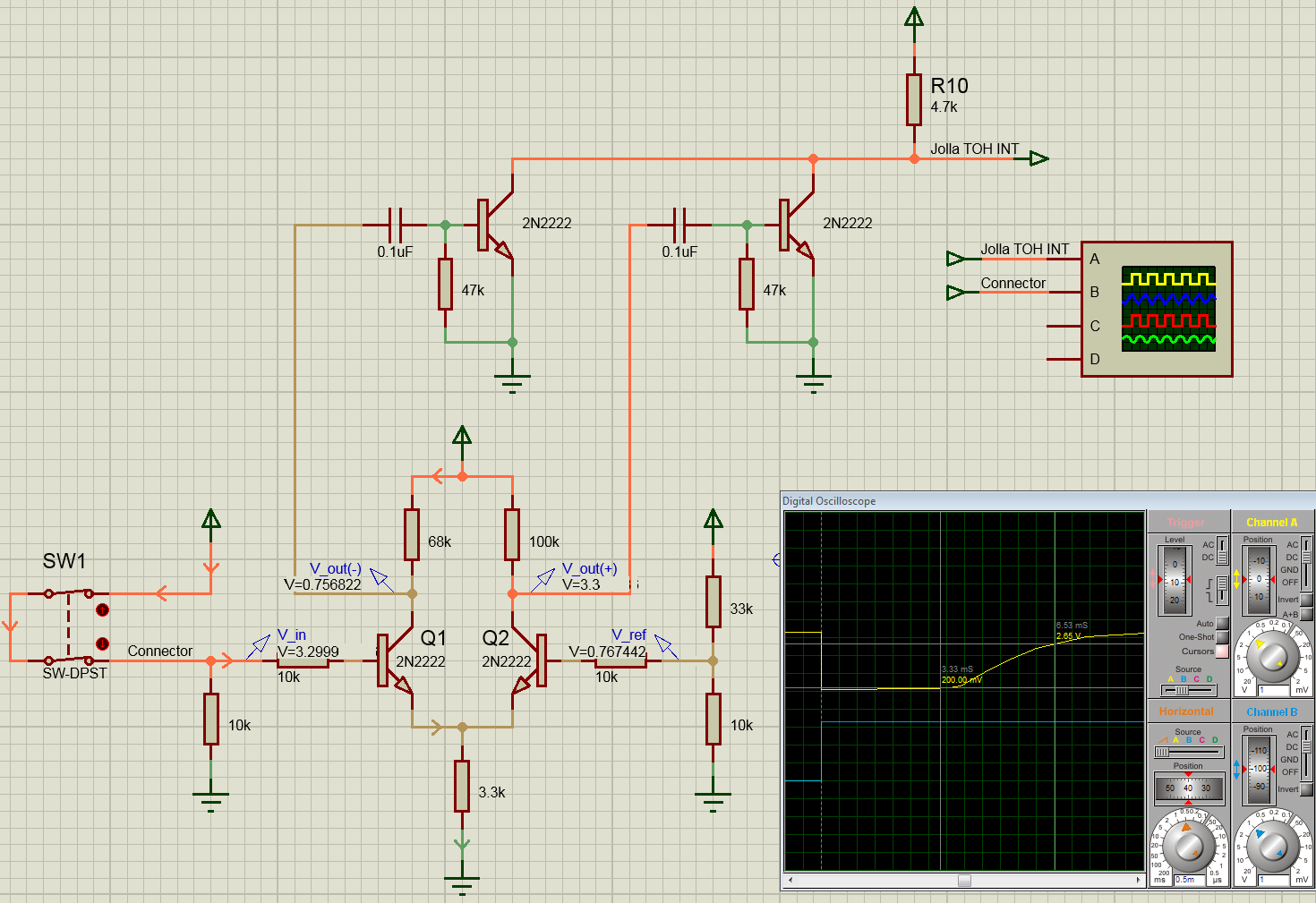
Discrete Circuit
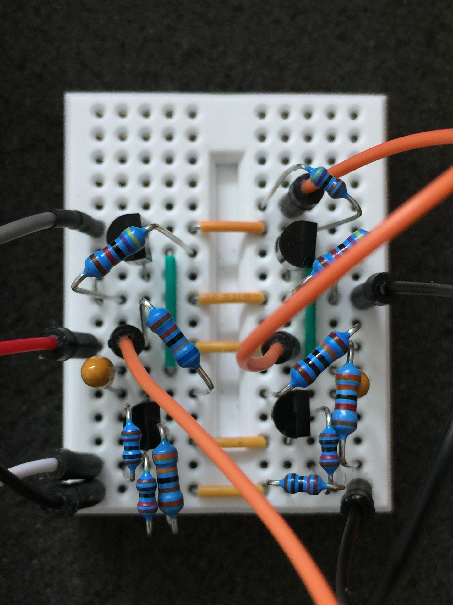 NPN circuit
Attach interrupt
In the simulation the voltage on the interrupt line is back at 2.65V after 6.5ms.
 NPN circuit - Attach interrupt simulation
In the experiment this value is reached after 6.8ms. The simulation is off by about 4%.
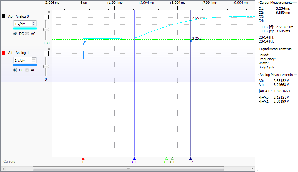 NPN circuit - Attach interrupt measurements
Detach interrupt
In the simulation the time until the interrupt line is back at 2.65V is 5.2ms. The signal is 25% shorter than the Attach interrupt.
 NPN circuit - Detach interrupt simulation
The measured time is 5.7ms (~19% shorter than the attach interrupt). Here the simulation is off by about 10%.
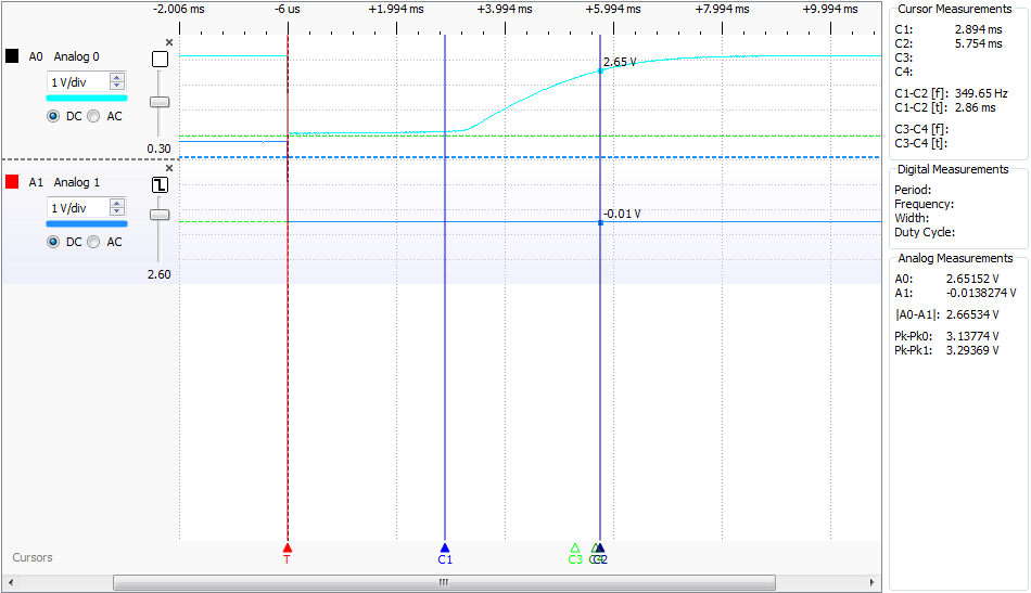 NPN circuit - Attach interrupt measurements
NPN circuit summary
The NPN circuit works fine. It is a cheap and simple solution to the problem, with parts that one most likely already has in store.
The differences between simulation and experiment are in a good region. If it is a problem that the detach interrupt is about 20% shorter than the attach interrupt remains to be seen. This problem could be solved by tweaking the R/C values in the driver stage.
To be able to "measure" intermediate values in the simulation has turned out to be quite a helpful tool debugging the circuit on the breadboard. So even for rather simple circuits like this I highly recommend it.
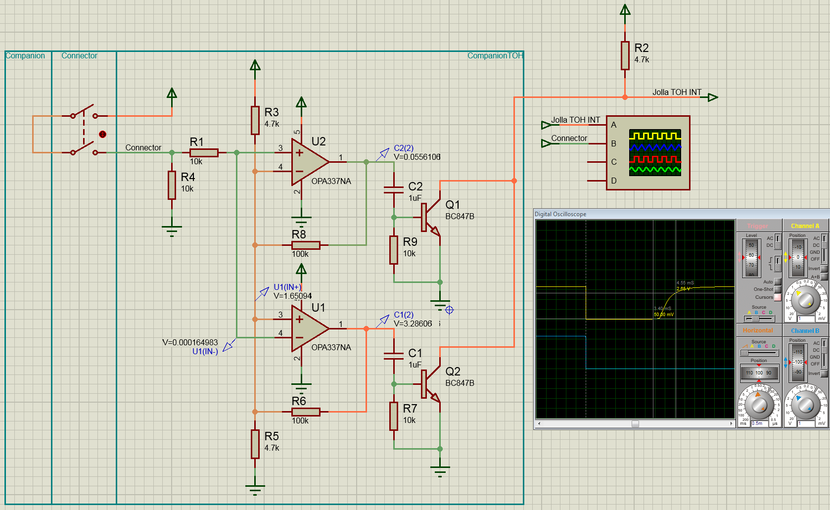
OPA Circuit
 OPA circuit
Attach interrupt
In the simulation the voltage on the interrupt line is back at 2.65V after 4.5ms.
 OPA circuit - Attach interrupt simulation
In the experiment this value is reached already after 3.5ms. The simulation is off by more than 28%.
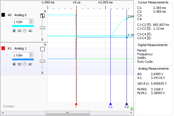 OPA circuit - Attach interrupt measurements
Detach interrupt
In the simulation the time until the interrupt line is back at 2.65V is 4.5ms - exactly the same as for the Attach interrupt.
 OPA circuit - Detach interrupt simulation
The measured time is ~3.1ms (~13% shorter than the attach interrupt). Here the simulation is off by more than 45%.
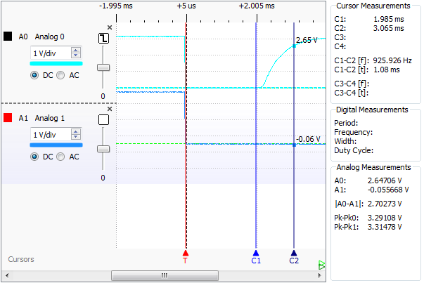 OPA circuit - Detach interrupt measurements
OPA circuit summary
This solution also works. Switching from low back to high is much faster than for the NPN circuit (Attach: 1.1ms (3.6ms NPN), Detach: 1.1ms (2,8ms NPN)). If this is an issue - we will see. If it is, one might consider using something like the LM393 comparator.
While there are significant differences between simulation and experiment, the simulation still was very useful for a quick prove of concept and getting the values "In the ball park". Whatever the reasons for the errors are (ideal model behaviour, not so ideal real part characteristics / experiments on bread boards, etc.), simulations and experiments have shown, that the circuit can be used to achieve the desired behaviour.
The optimal values for the capacitors and resistors can now easily be sorted out, experimenting with a prototype PCB and the Jolla.