Electronics
Dual Comparator Circuit with LM393
A comparator circuit proves quite useful, if you want to derive a digital signal from some analog input.
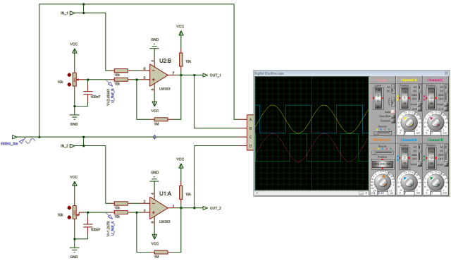
The one in the test circuit above, is made from one LM393 dual differential comparator IC.
- The upper and the lower circuits are identical and use one half of the LM393 each.
- Each of the halfs gets the same sinus wave 550Hz 5V input.
What is different, is how the reference values are set by the 10k poties.
- For the upper half V_Ref_B is set to 1/2 VCC (2.5V).
- V_Ref_A for the lower half is set to 1/4 VCC (1.25V).
The oscilloscope on the right side shows the effect in the simulation (remeber the invers logic!):
- OUT_1(B) goes high, if IN_1(A) falls below 2.5V and goes low on IN_1 above 2.5V.
- OUT_2(D) goes high, if IN_2(C) falls below 1.25V and goes low on IN_1 above 1.25V.
See how the RPM sensor signal for R1 was improved using this circuit.
