Electronics
Adafruit FeatherM0 ASF Tutorials
The source code for the tutorials can be found on GitHub.
02_RS232 - Serial Communication
The second project not only introduces the ASF SERCOM module, it also provides us with the basics for printing debug messages on a terminal or terminal emulator (like PuTTY on Windows).
 Schematic Source: Adafruit,
License: Attribution-ShareAlike Creative Commons
Schematic Source: Adafruit,
License: Attribution-ShareAlike Creative Commons
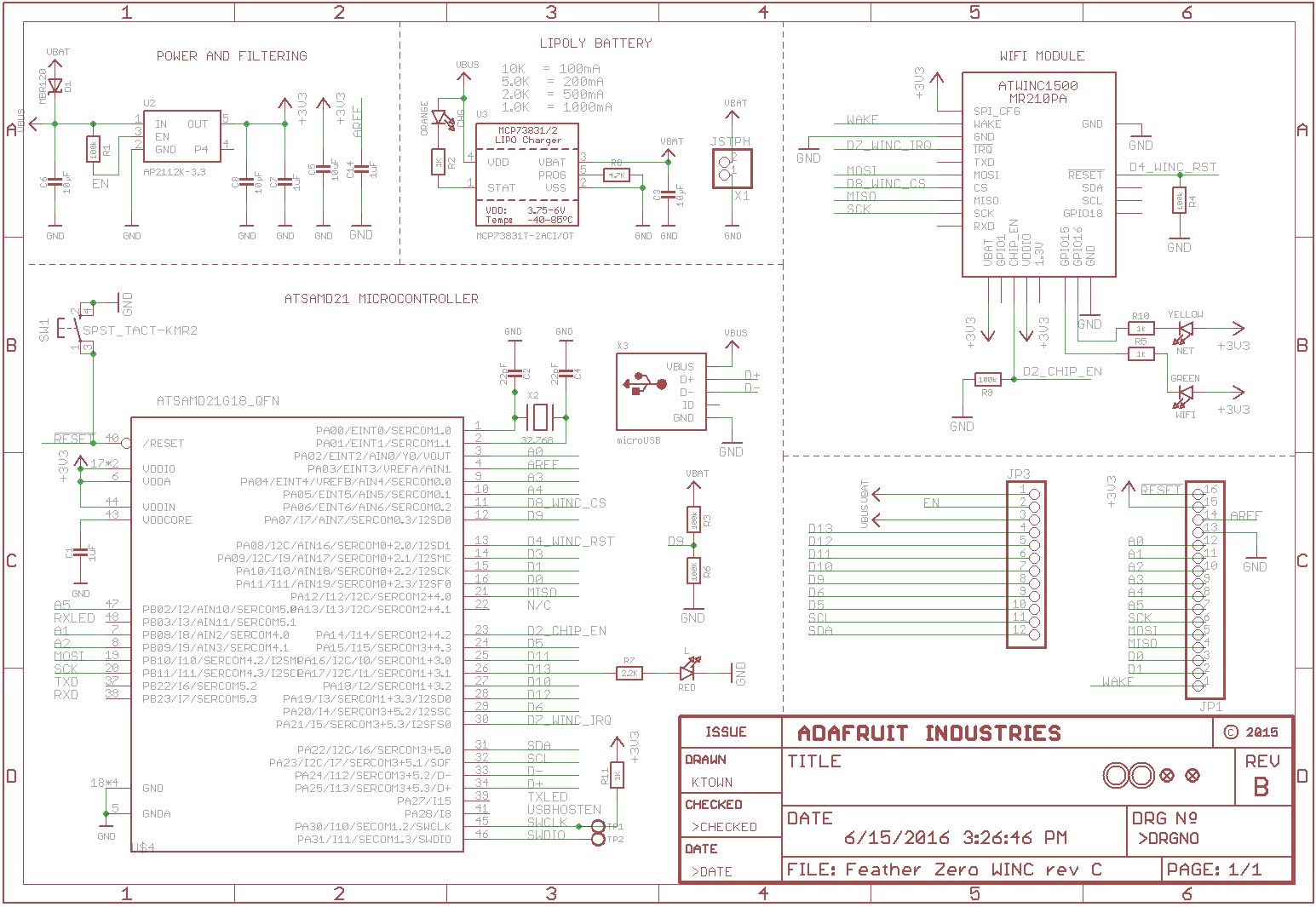
The schematic of Adafruit's FeatherM0_WiFi shows two pins on the ATSAMD21G18_QFN being labelled TXD (PB22, pin 37) and RXD (port PB23, pin 26).
If you look on the PCB there are two pins on JP1 (the longer header) also labelled TX (pin 2) and RX (pin 3).
Don't let them confuse you! The pins on the chip are not connected to the pins on this or any other header!
JP1.2 (TX)is labelledD1and connected toPA10 (SERCOM0+2.2, pin 15)on the MCUJP1.3 (RX)is labelledD0and connected toPA11 (SERCOM0+2.3, pin 16)on the MCU
The program will:
- Configure the SERCOM0 module as USART
- Print a welcome message
- Echo back every character you type on the terminal
- Flash the LED for every buffer transmitted from the board to the PC
Adding a new Atmel Software Framework (ASF) Skeleton Project
In project 01_Blink
we created a new Atmel Software Framework (ASF) project and the new Adafruit_FeatherM0_ASF_Tutorials Solution.
Now add a new ASF Skeleton Project for the 02_RS232 tutorial to this existing solution.
See my Step-By-Step tutorial if you are not sure how to do this.
Choosing a startup project
To make sure AtmelStudio always compiles and runs the 02_RS232 project we make it the StartUp Project.
- In AtmelStudio in the
Solution Explorerwindow right-click onSolution 'Adafruit_FeatherM0_ASF_Tutorials' - In the context menu choose
Set StartUp Projects...
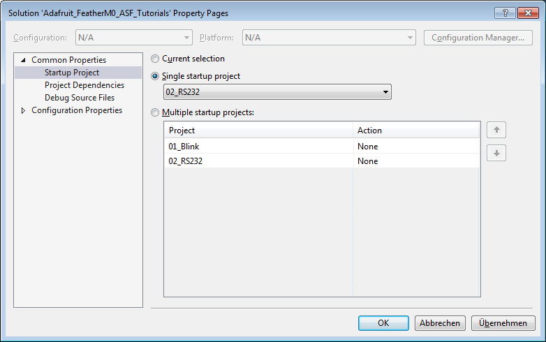
In the Solution 'Adafruit_FeatherM0_ASF_Tutorials' Property Pages dialog select
Single startup project02_RS232OK
Adding the project specific Atmel Software Framework (ASF) code
The next step is to import the ASF modules needed for the specific project.
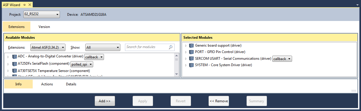
- Open the ASF wizard under
Project|ASF Wizard - Select Project
02_RS232
You should see two lists:
Available ModulesSelected Modules
In Selected Modules we already see:
Generic board support (driver)SYSTEM - Core System Driver (driver)
This is the standard framework needed for any ASF application.
For the LED to blink we need to control the PORT/Pin the LED is connected to.
So in Available Modules find:
PORT - GPIO Pin Control (driver)
Add>> the module to the project.
Also in Available Modules find:
SERCOM USART - Serial Communication (driver)
Add>> this module to the project.
Now press Apply. This will add all the necessary ASF code to our project.
Using the DIT Adafruit Feather Library
For this project we need to:
- Add the
Adafruit_FeatherM0_LED.hfile path to the include search path of you project - Link the
Adafruit_FeatherM0_LED.cfile to the project - Add the
Adafruit_FeatherM0_RS232.hfile path to the include search path of you project - Link the
Adafruit_FeatherM0_RS232.cfile to the project
See my Step-By-Step tutorial if you are unsure how to do this.
Writing the application code
In the Solution Explorer find the generated main.c.
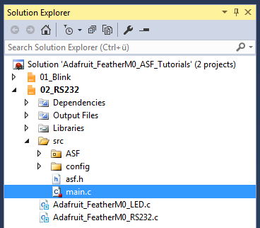

All we need to import to get the whole ASF magic working is the asf.h, that was generated by the ASF wizard.
The entry should already be there. The wizard took care of that for us (line 54).
- In line 55 I include the
Adafruit_FeatherM0_LED.hlibrary header file. - In line 56 I include the
Adafruit_FeatherM0_RS232.hlibrary header file.
- In line 62 we allocate a buffer for the characters received of the size we defined in line 58.
usart_on_received()
The lines 73..76 implement the callback function that we want the ASF USART module to call whenever the receive buffer is filled.
We use the function call in lines 75 to write back whatever character was received to the sender.
usart_on_transmitted()
The lines 87..90 implement the callback function that we want the ASF USART module to call whenever a buffer was transmitted.
We use the function call in lines 89 to toggle the on/off state of the LED in that case.
main()
The main function in lines 101..133:
- Initializes the board (line 109) and enables interrupts globally (line 110)
If you forget to enable the interrupts the callback functions will not work. - We use the DIT Adafruit Feather Library functions to:
- Configure the FeatherM0 LED pin (
LED_configure(), line 116) - Configure the FeatherM0 RS232 SERCOM (
RS232_configure(), line 118) - Configure and enable the
usart_on_received()callback that we want to be called by the usart, whenever the receive buffer is filled (RS232_configure_callback(), line 119) - Configure and enable the
usart_on_transmitted()callback that we want to be called by the usart, whenever it is finished transmitting a buffer (RS232_configure_callback(), line 120) - Enable the FeatherM0 RS232 SERCOM (
RS232_enable(), line 121)
- Configure the FeatherM0 LED pin (
- In line 127 we define the welcome message
- In line 128 we send the welcome message out
- Finally we enter an infinite loop (lines 1130..132) and read any characters that might have been sent to us (line 131)
Remember:
- Every time we received enough characters to fill our
rx_buffer,usart_on_received()gets called.
Since our buffer is currently of size 1, this means the function gets called for every single character received. - Every time we transmitted a buffer
usart_on_transmitted()gets called.