Robotics
R1 Motor Control (1)
OK, we do have the chassis and motors.
Now we some how have to get the motors turning. Preferrable without switching them on an off all the time by hand or remote control, since that does not really count as robotics, but as cheeting.
Microcontrollers
What I want, is a micro controller unit (MCU) to have control over the motors, since that's what I intent to use as my robots "brain".
There are plenty of MCUs on the market, each having a destinct set of features. In contrast to the central processing unit (CPU) of a PC (that should be able to do just about anyting), MCUs are usually used in highly specialized applications.
In the end this means, that:
- CPUs are complex and expensive, but they are powerfull and have universal use
- MCUs are much more simple than CPUs and a lot cheaper, they need less energy, but have less of a punch and need to be selected for the purpose
These days a lot of different platforms make it easy to start working with MCUs.
First I decided for the Arduino/Genuido UNO platform, mainly because it is "cheep and available" and I found this great book for beginners by Elliot Williams called Make: AVR Programming. Also everyone is using it, so you find a lot of support on the net.
After the first few experiments, I stoped using the Arduino (except as a programmer), but started using the MCU it is based on, the Atmel ATmega328P, directly on a bread board (don't worry, the book pretty much does the same).
The 328P is so simple to use, hard to kill and cheap to replace, that I did not see any added value in using the Arduino.
Also, working with the MCU directly teaches you a lot of things you want learn anyway, if you are serious about building your own robot.
So my advice is:
- skip the Arduino
- Make: AVR Programming
- a hand full ATmega328P (just in case :)
- a bread board and the parts described by the chapters of the book
- the free of charge Atmel Studio IDE
- an AVR Dragon (instead of the Arduino) as the programmer
Digital Motor Control by PWM
If you try to drive a motor from am MCU, you have to solve the problem, that MCUs are digital devices, while motors are analog.
While most MCUs have build in digital to analog converters (ADCs), this turns out not to be the most efficient solution.
There is a much simpler trick to control motors by digital means.
Normal DC motors have what is called inertia. That means if you switch on or off the power, the motor will not start or stop immediately, but needs time to accelerate or slow down. If you do it really fast, the motor cannot follow the switch at all. It will only "see" the power derlivered during the ON-time in an ON/OFF-duty cycle. This power (minus whatever is needed to overcome the system's friction), defines how fast the motor runs. So by variating the ON/OFF-time ratio in a constant (fast) duty cycle, you can control the motor speed with a digital switch.
This concept is called Pulse With Modulation (PWM).
And since it is based on discrete states, PWWM is quite easy to implement with digital computers. As it is widely used in embedded systems, most MCUs even have specialized hardware on board, to relieve the main routine from running the task.
H-Bridge
While with PWM we can control the motor's speed, the motor will unfortunately only run in one direction.
For a DC motor to change direction means to change the polarity of the power source, which cannot be done by a control pin of an MCU.
Or can it?
Believe it or not: Someone else already run into the same problem trying to drive motors from a MCU.
One of the common solutions is to use a circuit that is called H-Bridge.


There are tons of articles on the net, describing the working principle of a H-Bridge. So I will not get into the details here.
Actually it is so common, that specialized ICs exist for different motor numbers an power requirements.
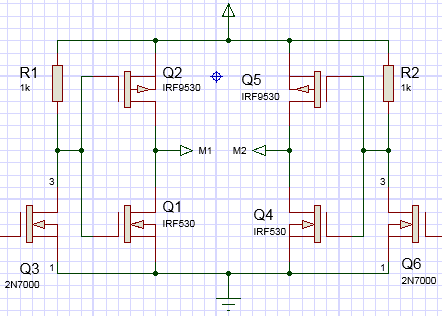
But again, for my own educational purpose, I decided to follow the book and build a discrete version using discrete Metal Oxide Semiconductor Field Effect Transistors (MOSFETs).
Beside some more technical issuses (like you can shortcut it, by closing the wrong switches at the same time - shot-through), the circuit as shown above uses 4 MCU I/O lines. Somehow these I/O lines are always on short supply on an MCU. So you don't want to do this.
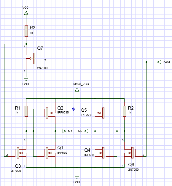
If we switch 2 of the N-type MOSFETS for P-types and add a few resistors and 2 more 2N7000 as drivers for each side of the bridge (there is no such thing like "Free lunch"), we can get down to 2 I/O lines on the MCU, using the following circuit.
These circuits are from Elliot Williams book. Also there, he shows that with the so called "Locked Anti-Phase" circuit we can even get down to 1 I/O line.
Beware, that for the bridge MOSFETS (the IRFs) you have to use types, that can handle the power you want send through the motor.
I use 2N7000 for all the other supporting switch MOSFETs. This is a general purpose type you can use for just about anything, that has no special demands. They are cheap and I suggest you always have a dozend or so laying around.
The circuit as a few properties, you should be aware of:
- The motor now stands still on a 50/50 PWM cycle (not on the 0% ON-time cycle anymore).
- You loose half of the PWM resolution, but gain direction and speed control over a single wire / MCU I/O-port.
- Even if it stands still, the motor will draw a little current (not nearly as much as when running so).
- There is a constant noise from the motor, even if it is not turning (depending on the PWM duty cycle and of course you ears, you can hear it).
- As long as the power is on, the motor has breaks. It will keep standing still (even if e.g. the robot stands on a slope), if you send a 50/50 PWM cycle (within limits of course :).
R1 H-Bridge
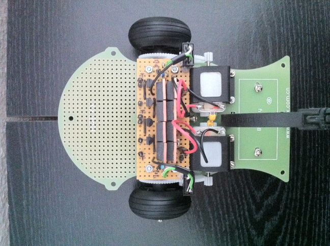
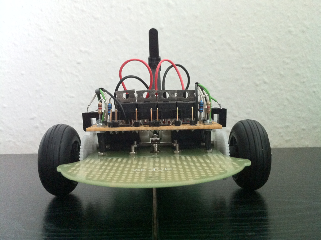
For the R1 I build two (one for each motor) discrete H-Bridges on a prototype board, using the circuit without the Locked Anti-Phase.
I did not integrate the Locked Anti-Phase circuits into the board, because:
- There was just no more room. Since I also needed space for some sensors, I'll describe in the next part.
- Initially I had some problems getting the Lock Anti-Phase circuit running, until I found out, that the value of the R3 pull-up resistor of 10k in the book is most likely wrong. Since I changed it to 1k, everything works stable.
- Finally I wasn't so sure at the beginning, if I always want to use the circuit in the Locked Anti-Phase configuration.
So thats what it looks like now: