Electronics
LIDAR Lite2 - How to use I2C without Arduino
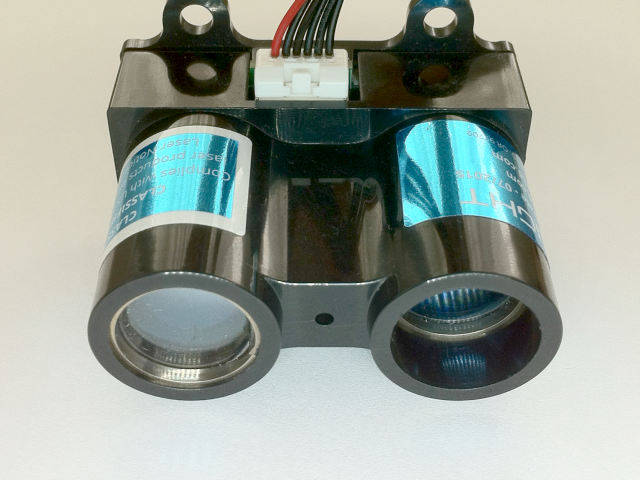
A couple of month ago I bought a LIDAR Lite 2 (aka blue label) made by Pulsed Light, which I intent to use as the main sensor for Simultaneous Localization and Mapping (SLAM) in my robotic projects.

LIDAR-Lite2 Specifications
| General | Technical Specifications |
|---|---|
| Power | 4.75-5.5V DC Nominal, Maximum 6V DC |
| Weight | PCB 4.5 grams, Module 22 grams with optics and housing |
| Size | PCB 44.5 X 16.5mm (1.75" by .65") |
| Housing | 20 X 48 X 40mm (.8" X 1.9" X 1.6") |
| Current Consumption | <2mA @ 1Hz (shutdown between measurements), <100mA (continuous operation) |
| Max Operating Temp. | 70°C |
| External Trigger | 3.3V logic, high-low edge triggered |
| PWM Range Output | PWM (Pulse Width Modulation) signal proportional to range, 1msec/meter, 10µsec step size |
| I2C Machine Interface | 100Kb - Fixed, 0xC4 slave address. Internal register access & control. |
| Supported I2C Commands | Single distance measurement, velocity, signal strength |
| Mode Control | Busy status using I2C, External Trigger input / PWM outputs |
| Max Range under typical conditions | ~40m |
| Accuracy | +/- 2.5cm (+/- ~1") |
| Default Rep Rate | ~50 Hz |
Protocol Spying
These days you find a lot of documentation on their GitHub page.
But when I started there was pretty much only a few wiring diagrams and the Arduino Library. And while the Arduino is a great tool, it is not always the right tool for the job. So the idea here is to learn how to use the LIDAR independent of it.

Fortunately you can control the LIDAR via I2C.
Just exactly how to do it was a little difficult to find out from the information at hand.
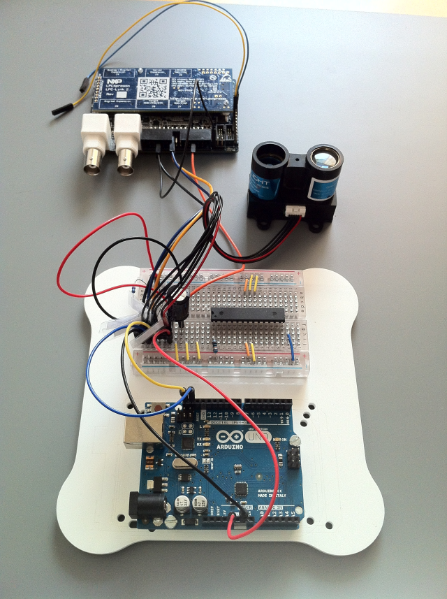
So I got out my old friend the Logic Analyser and started with some reverse engineering on the wire.

While the communication between Arduino and LIDAR kind of worked (not especially stable though), as soon as the Logic Analyser was attached, the Arduino would not talk to the LIDAR anymore.
NO, this is NOT an anti-spy protection. The additional capacity of the Logic Analyser lines probably just was to much for the I2C bus.
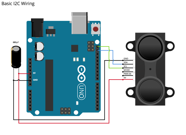
What the "Basic I2C Wiring" diagram is not showing is, is that the I2C bus is usually terminated by a pull-up resistor on each of the lines SCL and SDA.
The calculation can become quite interesting (i2c-bus.org has all the details).
To fix my problem I used some precalculated value from the Cypress PSoC Creator Component Datasheet for the Serial Communication Block.
| Standard Mode | Fast Mode | Fast Mode Plus | Units |
|---|---|---|---|
| 0-100kbps | 0-400kbps | 0-1000kbps | |
| Ohm |
They say, that: "These values work for designs with 1.8V to 5.0V VDD, less than 200pF bus capacitance (CB), up to 25µA of total input leakage (IIL), up to 0.4V output voltage level (VOL), and a max VIH of 0.7 * VDD."
Since the LIDAR Lite2 is specified for 100kbps I used two 4.7k resistors.
Fun Fact: Later on I was able to use the LIDAR with this I2C bus configuration and the Cypress board, with bus speeds up to 1000kbps without problems.
Finally we can "spy" on the communication:
- A RESET command is send to the LIDAR, by writing 0x00 to the Command Control Register (0x00) at LIDAR's I2C address 0x62

This reboots the FPGA and loads the default values from the Flash memory.
- The measurement delay is set, by writing 0x04 to Measurement Delay Register (0x45)

What the documentation is saying is:
- Measurement Delay - Sets the time between measurements. 0xc8 corresponds to 10Hz while 0x13 corresponds to 100Hz. Minimum value is 0x02 for proper operation.
So that would be: 100ms delay for 0xc8 (10 measurements per second), 10ms delay for 0x13
The Measurement Frequency for other than the given values can be calculated by Linear Interpolation using the values given.
Here some examples:
0x02 ~1.55Hz (minimum value allowed for stable operation) 0x04 ~2.54Hz 0x08 ~4.53Hz - The Velocity Scale Factor flag (Bit 5) in the Mode Control Register (0x04) must be set to operate at any non-default value.
The measurement time will ultimately limit the maximum achievable rate in burst or continuous operation.The documentation does not state what the default value for the Measurement Delay Register (0x45) is, but for the Mode Control Register (0x04) it is 0x00, resulting in a fixed measurement delay of 100ms, independent of the value of the Measurement Delay Register.
- Measurement Delay - Sets the time between measurements. 0xc8 corresponds to 10Hz while 0x13 corresponds to 100Hz. Minimum value is 0x02 for proper operation.
- Register 0x04 is the Mode Control Register
This is a bit flag register with the default value of 0x00:
Bit Function 7 Velocity Enable velocity measurement 6 Inhibit Reference "1" inhibits the acquisition of reference pulses reducing measurement times and reducing measurement variations at the expense of decreasing accuracy over time.
"0" allows normal operation5 Velocity Scale factor Also used to set delay between measurements in burst/continuous measurement mode "1" sets the velocity measurement separation to a frequency set by Measurement Delay Register (0x45) resulting in a velocity scale of meters/sec.
"0" value results in a measurement separation of 100msec. Velocity scale is decimeters/sec.4 Disable reference filter Reference Filter averages 8 reference measurements for reduced measurement variability 3 Disable short signal acquisition runs to the correlation limit of 250 2 Disable short reference allows reference maximum count from reference acquisition count register rather than default value of 0x05 1 CLK SHUT 0 Preamp Off 
The command set Bit 0 and Bit 5, switching the Preamp Off and giving the Measurement Delay Register (0x45) control over the measurement frequency.
Velocity measurement is 'Off', so the Velocity Scale does not matter.
- In the final step of the initialization the Outer Loop Count (register 0x11) is set to 0xFF

The Outer Loop Count allows multiple measurements with a single measurement command.
- If set to - '0xff', continuous measurement will be performed.
- A value of less that 0xff will terminate continuous measurement after that amount of measurments (ex. 0xfe will take 254 measurements and stop).
- Now the measurement is started by writing 0x04 (Take acquisition & correlation processing with DC correction) to the Command Control Register (0x00)

- The registers 0x0f and 0x10 have to be read to get the two byte distance measurement from the LIDAR

Using LIDAR's auto increment capability this can be done in one call.
Auto Increment is activated by setting the Most Significant Bit (MSB) in the register address.
So, to read the register 0x0f and 0x10 in one call we address the register 0x8f (0x0f with MSB set to 1 = 0x8F => LIDAR register auto increment) .
As it is standard for operating the I2C bus:
- The register address to read is written to the LIDAR I2C address, without a
Stop - A
Restartsignal is issued - The
Readcommand is send to LIDAR's I2C address, fetching the two bytes from 0x0f and 0x10. - The
NACKsignal send by the Arduino ends the data transfer from the LIDAR (Stop).
- The register address to read is written to the LIDAR I2C address, without a
Step number 6 from now on is repeated indefinitely

Now its time to put the new knowledge to the test.
I will try to use the LIDAR with a Cypress PSoC CY8C4247LQI-BL483 in the next part.