Electronics
Adafruit FeatherM0 ASF Tutorials
The source code for the tutorials can be found on GitHub.
06_WINC1500_WiFi
The goal of this project is to get familiar with the Atmel WINC1500 WiFi module, that the FeatherM0-WiFi is equipted with.
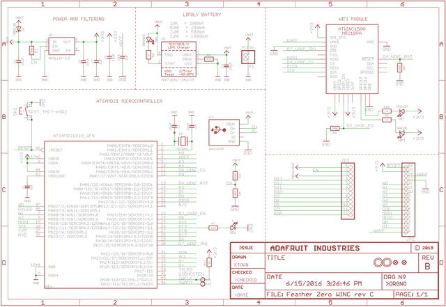 Schematic Source: Adafruit,
License: Attribution-ShareAlike Creative Commons
WINC1500 module versions
So far I have seen two versions of the module:
ATWINC1500-MR210PAOn my Atmel WINC1500 eXplained board
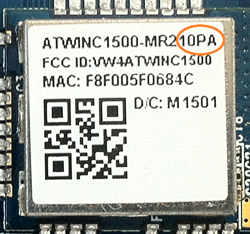
ATWINC1500-MR210PBOn my FeatherM0-WiFi
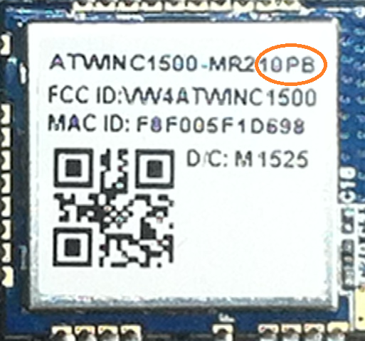
In contrast to what the Adafruit schematic claims, my FeatherM0-WiFi has a version B module.
That is a good thing!
Only the version B modules are capable of running the latest firmware, needed for the latest Atmel Software Foundation versions.
You can find out more about the module versions and how to upgrade the WINC1500 firmware in my article FeatherM0-WiFi - WINC1500 Firmware Upgrade.
FatherM0-WiFi SAMD21 MCU - WINC1500 module interface
The following table lists the connections between the FatherM0 ATSAMD21G18 MCU and the WINC1500 WiFi module on the FatherM0-WiFi:
The ATSAMD21G18 on the FeatherM0-WiFi uses it's SERCOM4 in SPI mode to communicate with the WINC1500 module.
| ATSAMD21G18 | WINC1500 | |
|---|---|---|
| PA08 | WINC1500 !RESET | active low |
| PA14 | WINC1500 CHIP_EN | |
| PA21 | WINC1500 !IRQ | active low |
| PA06 | SPI CS | SPI chip select |
| SERCOM4.0 (PA12) | SPI MISO | serial data from WINC1500 to MCU |
| SERCOM4.2 (PB10) | SPI MOSI | serial data from MCU to WINC1500 |
| SERCOM4.3 (PB11) | SPI SCK | SPI serial clock (MCU driven) |
While the WINC1500 module also features I2C and a serial debug interface, none of these are connected to the MCU or any header.
Software
The program will:
- Configure the SERCOM0 module as USART for sending messages to a terminal
- Print a welcome message to the terminal
- Configure the SERCOM4 module and some MCU pins for the communication with the WINC1500
- Initialize the WINC1500 ASF service
- Use the WINC1500 ASF service to scan for all WiFi Access Points available
- Connect to the preconfigured WiFi Access Point
- Obtain an IP address for the WiFi network using DHCP
Adding a new Atmel Software Framework (ASF) Skeleton Project
Add a new ASF Skeleton Project for the 06_WINC1500_SPI_ASF_3.34 tutorial to the existing solution.
See my Step-By-Step tutorial if you are not sure how to do this.
Choosing a startup project
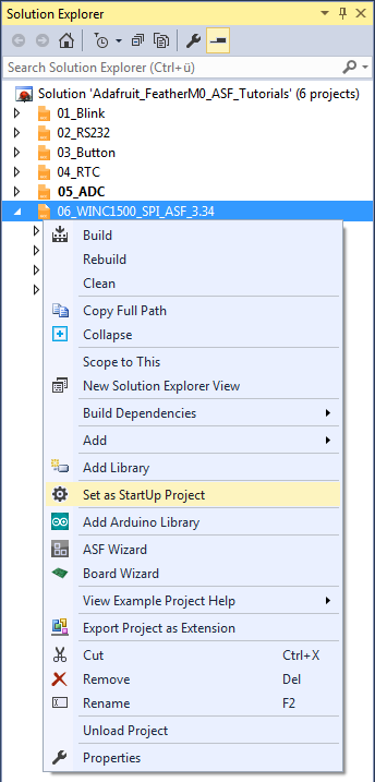
To make sure AtmelStudio always compiles and runs the 06_WINC1500_SPI_ASF_3.34 project we make it the StartUp Project.
- In AtmelStudio in the
Solution Explorerwindow right-click on06_WINC1500_SPI_ASF_3.34 - In the context menu choose
Set as StartUp Project
Adding the project specific Atmel Software Framework (ASF) code
The next step is to import the ASF modules needed for the specific project.
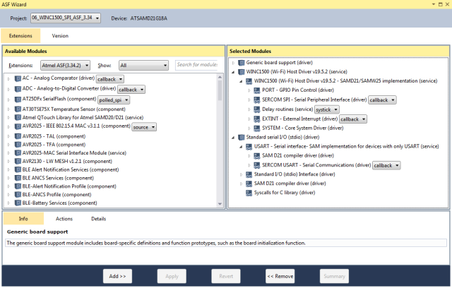
- Open the ASF wizard under
Project|ASF Wizard - Select Project
06_WINC1500_SPI_ASF_3.34
or use the ASF Wizard entry in 06_WINC1500_SPI_ASF_3.34's context menu.
You should see two lists:
Available ModulesSelected Modules
In Selected Modules we already see:
Generic board support (driver)SYSTEM - Core System Driver (driver)
This is the standard framework needed for any ASF application.
In Available Modules find:
WINC1500 (Wi-Fi) Host Driver (service)
Add>> the module to the project.
This driver provides the WINC1500 service routines.
It also already includes the services and drivers for:
- PORT
- SERCOM SPI
- Delay routines
- EXTINT
- SYSTEM
Next find in Available Modules :
Standard serial I/O (stdio) (driver)
Add>> this module to the project.
While this driver is strictly speaking not necessary for the project,
it provides the printf() function for printing to the serial terminal,
making printing messages more convenient.
This driver also includes the
- USART (service), that includes the SERCOM USART driver
Now press Apply. This will add all the necessary ASF code to our project.
Using the DIT Adafruit Feather Library
For this project we need to:
- Add the
Adafruit_FeatherM0_RS232.hfile path to the include search path of you project - Link the
Adafruit_FeatherM0_RS232.cfile to the project
See my Step-By-Step tutorial if you are unsure how to do this.
SPI Setup
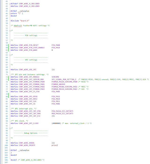
The WINC1500 ASF service module adds the file config/conf_winc.h to the project.
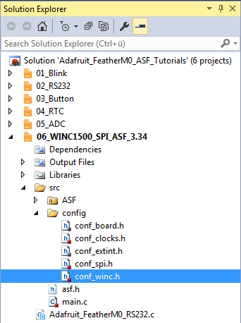
Here we need to define the SPI connection between the MCU and the WINC1500.
Since on the FeatherM0-WiFi the MCU and the WINC1500 are hard wired, we use the following configuration.
- The
!RESETandCHIP_ENABLEset-up is strait forward (lines 59 and 60). - The
WAKEpin of the WINC1500 is not connected to the MCU on the FeatherM0-WiFi (line 61), but it is connected to JP1-1, if needed.
The way the FeatherM0-WiFi is designed, SERCOM4 is the natural choice for the MCU-WINC1500 SPI communication. Line 72 configures the WINC1500 ASF service to use SERCOM4.
ATSAMD MCUs are quite flexible when it comes to what internal component is connected to what external connection pin and how. The drawback of such a flexibility is, that one has to configure the connections.
One can get the necessary information from the MCU's datasheet, but reading these is a pain in the neck. You get the feeling, that for programming a SAMD you have to know everything before you can do anything and with 1111 pages that is no fun.
Finding the MCU's datasheet and the SPI Application Note little helpful, I began searching the ASF source code.
Lucky enough this time (in ASF spi.h line 1468ff.) someone took the time to properly document the SPI mux settings in two tables.
For SPI Master mode (which we will use):
| Combination | DOPO / DIPO | SERCOM PAD[0] | SERCOM PAD[1] | SERCOM PAD[2] | SERCOM PAD[3] |
|---|---|---|---|---|---|
| A | 0x0 / 0x0 | MOSI | SCK | - | - |
| B | 0x0 / 0x1 | MOSI | SCK | - | - |
| C | 0x0 / 0x2 | MOSI | SCK | MISO | - |
| D | 0x0 / 0x3 | MOSI | SCK | - | MISO |
| E | 0x1 / 0x0 | MISO | - | MOSI | SCK |
| F | 0x1 / 0x1 | - | MISO | MOSI | SCK |
| G | 0x1 / 0x2 | - | - | MOSI | SCK |
| H | 0x1 / 0x3 | - | - | MOSI | SCK |
| I | 0x2 / 0x0 | MISO | SCK | - | MOSI |
| J | 0x2 / 0x1 | - | SCK | - | MOSI |
| K | 0x2 / 0x2 | - | SCK | MISO | MOSI |
| L | 0x2 / 0x3 | - | SCK | - | MOSI |
| M | 0x3 / 0x0 | MOSI | - | - | SCK |
| N | 0x3 / 0x1 | MOSI | MISO | - | SCK |
| O | 0x3 / 0x2 | MOSI | - | MISO | SCK |
| P | 0x3 / 0x3 | MOSI | - | - | SCK |
For SPI Slave Mode (reference only):
| Combination | DOPO / DIPO | SERCOM PAD[0] | SERCOM PAD[1] | SERCOM PAD[2] | SERCOM PAD[3] |
|---|---|---|---|---|---|
| A | 0x0 / 0x0 | MISO | SCK | /SS | - |
| B | 0x0 / 0x1 | MISO | SCK | /SS | - |
| C | 0x0 / 0x2 | MISO | SCK | /SS | - |
| D | 0x0 / 0x3 | MISO | SCK | /SS | MOSI |
| E | 0x1 / 0x0 | MOSI | /SS | MISO | SCK |
| F | 0x1 / 0x1 | - | /SS | MISO | SCK |
| G | 0x1 / 0x2 | - | /SS | MISO | SCK |
| H | 0x1 / 0x3 | - | /SS | MISO | SCK |
| I | 0x2 / 0x0 | MOSI | SCK | /SS | MISO |
| J | 0x2 / 0x1 | - | SCK | /SS | MISO |
| K | 0x2 / 0x2 | - | SCK | /SS | MISO |
| L | 0x2 / 0x3 | - | SCK | /SS | MISO |
| M | 0x3 / 0x0 | MISO | /SS | - | SCK |
| N | 0x3 / 0x1 | MISO | /SS | - | SCK |
| O | 0x3 / 0x2 | MISO | /SS | MOSI | SCK |
| P | 0x3 / 0x3 | MISO | /SS | - | SCK |
Note: If MISO is unlisted, the SPI receiver must not be enabled for the given MUX setting.
So line 73 defines, what SERCOM4 SPI signal ends up on what pad.
Since not each pad can be connected (mux'ed) to every pin, one has to select a Combination that works with the PINMUX setting available
for SERCOM4 and the hardware set-up given.
In lines 74..77 we now connect the SERCOM4 SPI signal pads to the external pins, the WINC1500 SPI signal lines are connected to.
Next, lines 78..83 map the pins the WINC1500 module is actually connected to on the FeatherM0-WiFi, to some abstract names used by the ASF WINC1500 service.
Since the WINC1500 module uses an interrupt line to notify the MCU, we need to configure the pin of the MCU this line is connected to and set-up the External Interrupt Channel (EIC) (lines 86..88).
In line 91 the SPI bus clock speed is defined. Note the limit for the frequency of 1/2 MCU frequency.
Writing the application code
In the Solution Explorer find the generated main.c.
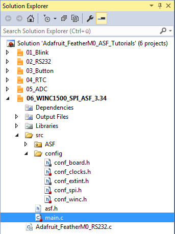
All we need to import to get the whole ASF magic working is the asf.h, that was generated by the ASF wizard.
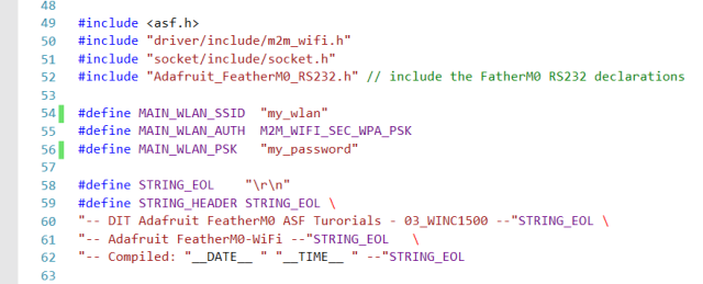
The entry should already be there. The wizard took care of that for us (line 49).
- Lines 50 and 51 include the header files we need to be able to work with the ASF WINC1500 service.
- In line 52 we include the
Adafruit_FeatherM0_RS232.hlibrary header file.
The lines 54..56 define the WLAN access parameters. Of course you have to use your own settings here.
- In line 58 I have defined a symbolic name for the end of line characters of a string.
- Lines 59..62 define the welcome message, the program should print to the terminal at startup.
The compiler replaces__DATE__and__TIME__with the current date and time at compilation time.
Quite convenient, if you have to figure out what version of your software your board is actually running.
In line 65 we define a global variable for this compilation unit, that we remember the index of the next access point scan result in. This needs to be a global variable, so the different call back functions have access to it.
main()
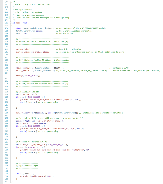
To better understand how to work with the ASF WINC1500 service, we start the explanation of the application code with the main() function in lines 252..312.
Lines 254..256 define a couple of variables, used by the main() function.
- Line 254 creates an instance of the SERCOM UART data structure
- Line 255 an instance of the WiFi initialization data structure
- Line 256 defines a variable for the return values of different calls
- Line 262 initializes the board
- Line 263 enables interrupts globally
If you forget to enable the interrupts the callback functions will not work. - We use the DIT Adafruit Feather Library functions to:
- Configure the FeatherM0 RS232 SERCOM (
RS232_configure(), line 269) - Enable the FeatherM0 RS232 SERCOM (
RS232_enable(), line 270)
- Configure the FeatherM0 RS232 SERCOM (
- Line 172 prints the welcome message to the serial terminal
Up to now, the code is pretty much known from the previous tutorials.
Now we start setting up the WiFi subsystem:
- Lines 279..284 initializes the board support package for the WINC1500 WiFi.
Since there is no point in continuing the program, if the initialization fails, we print an error messing and stop processing. - Line 286 initializes the WiFi initialization data structure with it's default values
- Line 289 assigns the call back function
wifi_on_status_changed()for events of the WiFi service. This function gets called by the WINC1500 service, whenever something interesting has happened in the WiFi subsystem, the main application should know about. - Lines 290..295 initializes the WiFi subsystem.
Again, since there is no point in continuing the program, if the initialization fails, we print an error messing and stop processing.
After a successful initialization of the WiFi subsystem:
- Lines 298..303 request the first scan for available WiFi access points (APs)
An here too: Since there is no point in continuing the program, if the initialization fails, we print an error messing and stop processing.
The WiFi service will now start creating events for everything that might be interesting for the application program.
- Line 310 in the infinite loop of lines 309..311 will forward those events to the event handler function
wifi_on_status_changed()we have configured in line 289.
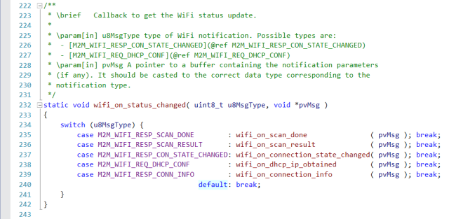
wifi_on_status_changed()
This is the function we configured to be notified when the ASF WINC1500 WiFi service has something to tell, that might be of interest for our application.
To keep the code readable, all this function is tasked with is:
- Figure out if any of the events we are interested in has occurred
- Forward the event to the handler specified for the specific event
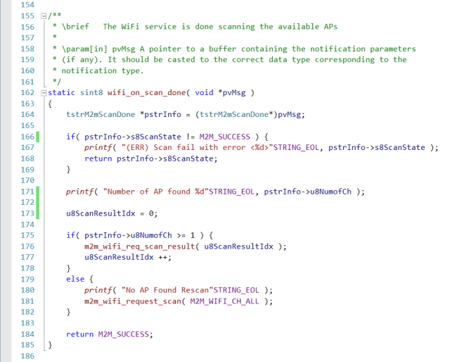
wifi_on_scan_done()
Since the main() function, just before it enters the infinite message handling loop, initiates a m2m_wifi_request_scan() for all channels in line 298,
the first event expected to occur is M2M_WIFI_RESP_SCAN_DONE, which results in a call to wifi_on_scan_done by
wifi_on_status_changed() (line 235).
This function:
- Defines a pointer variable for a scan_done results data structure and casts the pointer to the message received to it, to make the fields of the data structure accessible (line 164).
- Line 166 checks, if the scan for APs had any errors.
If an error was found:- Line 167 prints an error message and error code to the console
- Line 168 exits the function with the error code as return value
Otherwise:
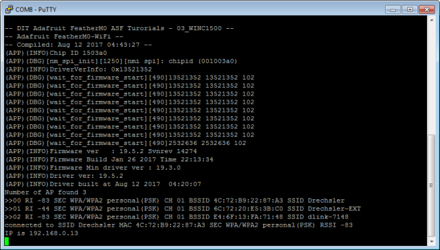
- Line 171 prints the number of WiFi Access Points found to the terminal
- Line 173 resets the global variable
u8ScanResultIdxthat denotes the index of the next Access Point to list - If any APs where found:
- Line 176 requests the scan results for the next Access Point denoted by
u8ScanResultIdx - and line 177 increases the index
Otherwise:
- Line 180 prints a message to the terminal
- and line 181 requests a new scan of all channels
- Line 176 requests the scan results for the next Access Point denoted by
If not aborted by a scan error in line 168, this function will always return a scan success state (line 184).
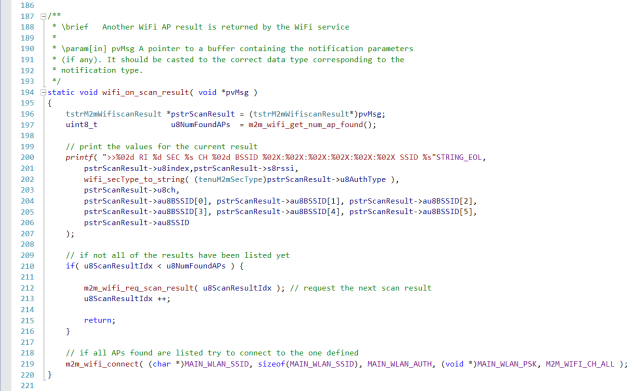
wifi_on_scan_result()
The call to m2m_wifi_req_scan_result( u8ScanResultIdx ) in wifi_on_scan_done() line 176,
will result in a M2M_WIFI_RESP_SCAN_RESULT event by the ASF WINC1500 service, once the result is available.
wifi_on_status_changed() will call this function,
when it receives the event message M2M_WIFI_RESP_SCAN_RESULT (line 236).
The function:
- Defines a pointer variable for a scan_result data structure and casts the pointer to the message received to it, to make the fields of the data structure accessible (line 196).
- Line 197 defines a variable, that the number of WiFi Access Points found in the last scan is assigned to.
This number only changes if a new scan is requested and otherwise stays the same between service API calls. - Lines 200..207 print different scan results for the current (
u8ScanResultIdx) WiFi Access Point, like:- Signal Strengths (RSSI)
- MAC address (BSSID)
- Station ID (SSID)
- Line 201 checks, if all the APs found in the last scan, have now been listed.
If not:- Line 212 requests the result for the next AP in the list (which will result in this function to be called again)
- line 213 increases the scan result index
- line 215 returns from the function
If all WiFi Access Points have been listed:
- Line 219 tries to connect to the AP that is specified by the values defined.
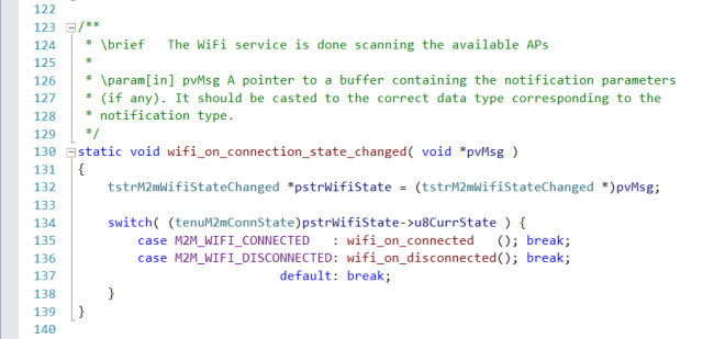
wifi_on_connection_state_changed()
The call to m2m_wifi_connect() in wifi_on_scan_result() line 219,
will result in a M2M_WIFI_RESP_CON_STATE_CHANGED event by the ASF WINC1500 service, once the connection is made.
Actually, any change in the connection state, after this initial m2m_wifi_connect() call, will result in a
M2M_WIFI_RESP_CON_STATE_CHANGED event by the ASF WINC1500 service.
wifi_on_status_changed() will call this function,
when it receives the event message M2M_WIFI_RESP_CON_STATE_CHANGED (line 237).
To keep the code tidy and readable, this function:
- Defines a pointer variable for a state change message data structure and casts the pointer to the message received to it, to make the fields of the data structure accessible (line 132).
- Makes a decision which connection state change event handler to call, based on the current state denoted in the message (line 134):
wifi_on_connected()is called, if the new state isM2M_WIFI_CONNECTED(line 135)wifi_on_disconnected()is called, if the new state isM2M_WIFI_DISCONNECTED(line 136)- any other state is ignored (line 137)
wifi_on_connected()
This function is called when the WINC1500 has successfully connected to the WiFi Access Point specified.
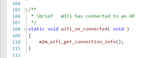
It calls the m2m_wifi_get_connection_info() function to gather more information about the AP the module is connected to (line 110).
wifi_on_dhcp_ip_obtained()
If the WINC1500 has successfully connected to the WiFi Access Point specified, the module automatically activated it's DHCP client, to obtain the network configuration and an IP address.
A M2M_WIFI_REQ_DHCP_CONF event is generated by the WINC1500 ASF service,
once the DHCP configuration is finished.
This event triggers wifi_on_status_changed() to call this function (line 238).
This function:
- Defines a pointer variable for a IP address message data structure and casts the pointer to the message received to it, to make the fields of the data structure accessible (line 150).
- Line 152 prints the obtained IP address to the terminal
wifi_on_connection_info()
The call to m2m_wifi_get_connection_info() in wifi_on_connected() line 110,
will result in a M2M_WIFI_RESP_CONN_INFO event by the ASF WINC1500 service, once the connection information is available.
wifi_on_status_changed() will call this function,
when it receives the event message M2M_WIFI_RESP_CONN_INFO (line 239).
This function:
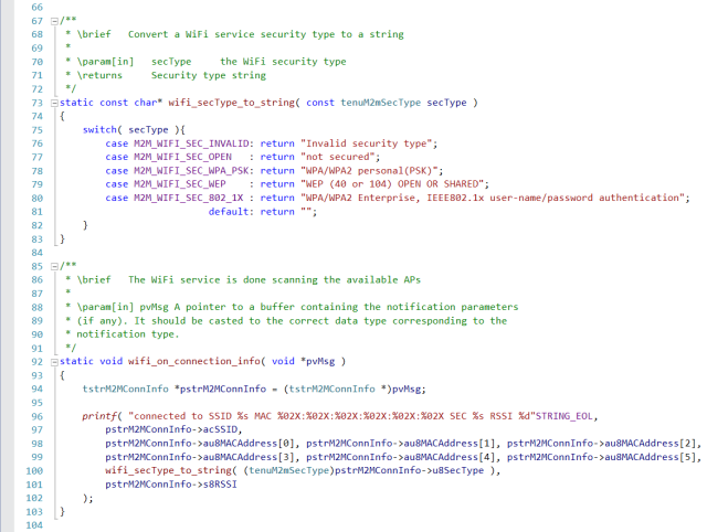
- Defines a pointer variable for a connection info message data structure and casts the pointer to the message received to it, to make the fields of the data structure accessible (line 94).
- Lines 96..102 print the connection information to the terminal.
It uses thewifi_secType_to_string()function (lines 73..83) to translate the security type of the WiFi network from it's numerical index to a human readable string.
wifi_on_disconnected()
This function is called when the WINC1500 has disconnected from a WiFi Access Point.
The function:
- Prints a status changed message to the terminal (line 118).
- Tries to reconnect to the AP specified (line 120).
