Electronics
Adafruit FeatherM0 ASF Tutorials
The source code for the tutorials can be found on GitHub.
04_RTC - Real Time Counter
The goal of this project is to get accustomed to the Real Time Clock counter of the ATSAMD21.
We will use it to toggle the LED at a period of three seconds.
Note:
We have toggled the LED in the projects before. But that was in the main loop of the program. So the MCU did pretty much nothing else. Hardly an efficient use of a 32bit ARM core. The goal of this project is to free up the main loop and have the RTC counter take care of the toggling.
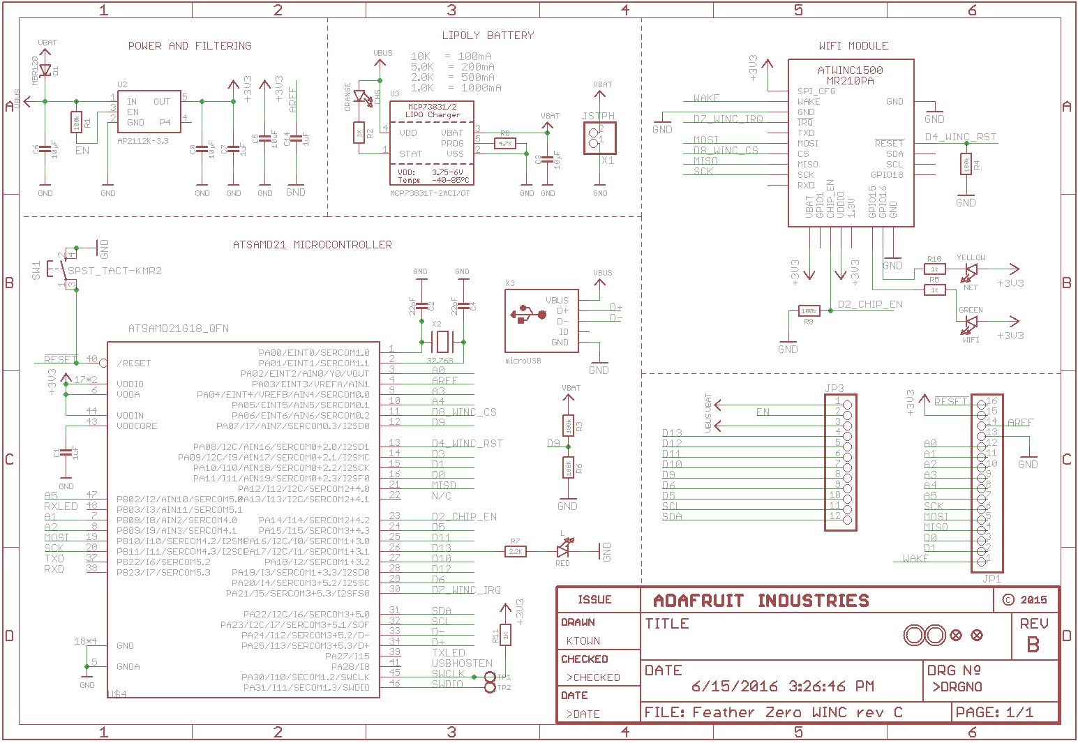 Schematic Source: Adafruit,
License: Attribution-ShareAlike Creative Commons
Schematic Source: Adafruit,
License: Attribution-ShareAlike Creative Commons
The program will:
- Configure the SERCOM0 module as USART for sending messages to a terminal
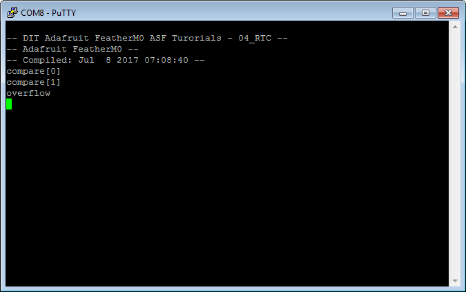
- Print a welcome message to the terminal
- Configure the Real Time Clock counter of the MCU
- Attach callback to different events of the RTC counter, that toggle the LED and send according messages to a terminal
Adding a new Atmel Software Framework (ASF) Skeleton Project
Add a new ASF Skeleton Project for the 03_Button tutorial to the existing solution.
See my Step-By-Step tutorial if you are not sure how to do this.
Choosing a startup project
To make sure AtmelStudio always compiles and runs the 04_RTC project we make it the StartUp Project.
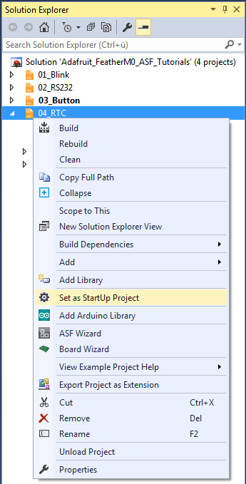
- In AtmelStudio in the
Solution Explorerwindow right-click on04_RTC - In the context menu choose
Set as StartUp Project
Adding the project specific Atmel Software Framework (ASF) code
The next step is to import the ASF modules needed for the specific project.
- Open the ASF wizard under
Project|ASF Wizard - Select Project
04_RTC
or use the ASF Wizard entry in 04_RTC's context menu.
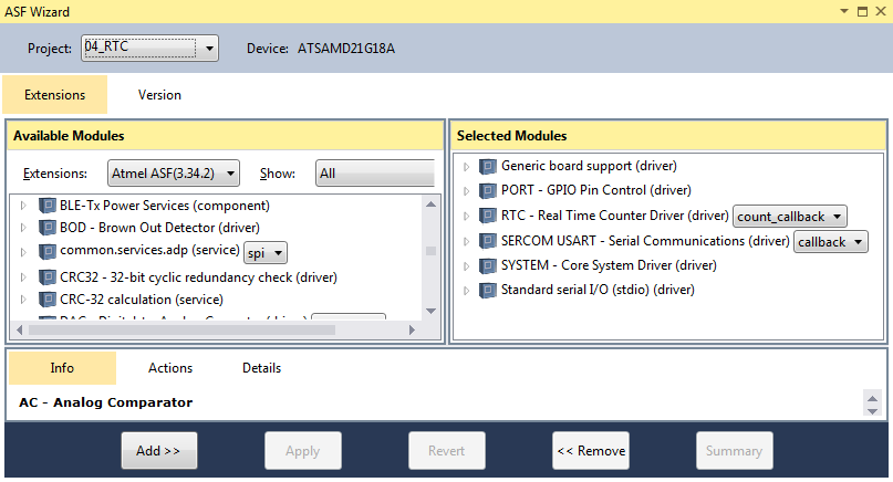
You should see two lists:
Available ModulesSelected Modules
In Selected Modules we already see:
Generic board support (driver)SYSTEM - Core System Driver (driver)
This is the standard framework needed for any ASF application.
In Available Modules find:
PORT - GPIO Pin Control (driver)
Add>> the module to the project.
This driver provides easy access to the I/O pins.
Now in Available Modules find:
RTC - Real Time Counter Driver (driver)
Add>> the module to the project.
This driver allows easy usage of the MCU Real Time Clock.
Also in Available Modules find:
SERCOM USART - Serial Communication (driver)
Add>> this module to the project.
Which helps us using a SERCOM module in USART mode.
And again in Available Modules find:
Standard serial I/O (stdio) (driver)
Add>> this module to the project.
While this driver is strictly speaking not necessary for the project,
it provides the printf() function for printing to the serial terminal,
making printing messages more convenient.
Now press Apply. This will add all the necessary ASF code to our project.
Using the DIT Adafruit Feather Library
For this project we need to:
- Add the
Adafruit_FeatherM0_LED.hfile path to the include search path of you project - Link the
Adafruit_FeatherM0_LED.cfile to the project - Add the
Adafruit_FeatherM0_RS232.hfile path to the include search path of you project - Link the
Adafruit_FeatherM0_RS232.cfile to the project
See my Step-By-Step tutorial if you are unsure how to do this.
RTC Clock Setup
The clock system of the ATSAMD21 is very versatile, but it also can be quite confusing to set up for a beginner. There are a couple of moving parts involved. They have to be set up correctly for the RTC to function properly.
We need to set up:
- A System Clock Source (
SYSTEM_CLOCK_SOURCE_XOSC32K)
These are the actual oscillators / crystals that provide the good vibrations.
Since the FatherM0 has especially for real time clock applications a 32.768kHz crystal attached to the MCU we are going to use it. - The Generic Clock Source (GCLK), the RTC is connected to (
GCLK_2).
- The connection between the
GCLK_2an theSYSTEM_CLOCK_SOURCE_XOSC32K
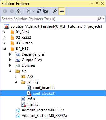
In the Solution Explorer find the generated conf_clocks.h.
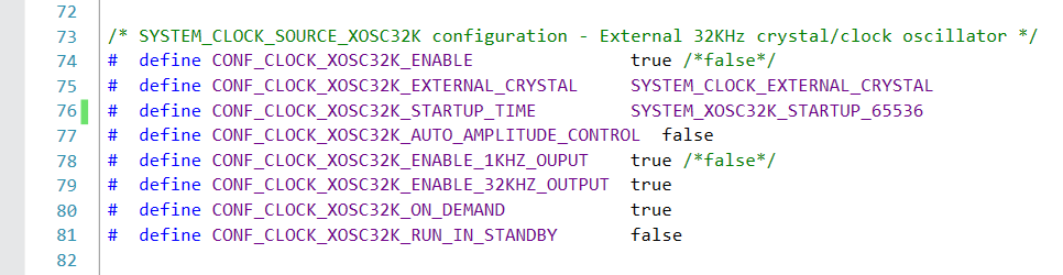
For step 1 find the SYSTEM_CLOCK_SOURCE_XOSC32K section. The following values worked for me:
For step 2 and 3 find the SYSTEM_CLOCK_SOURCE_XOSC32K section.
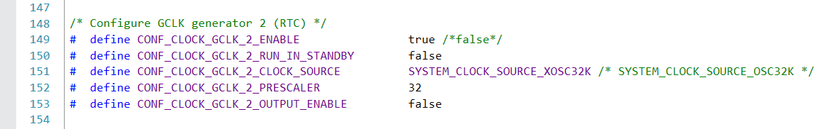
We enable the Real Time Clock generic clock source in line 149 and connect it to the SYSTEM_CLOCK_SOURCE_XOSC32K in line 151.
Writing the application code
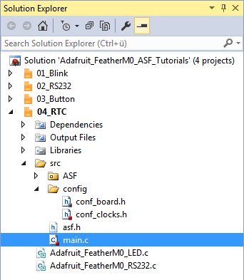
In the Solution Explorer find the generated main.c.
All we need to import to get the whole ASF magic working is the asf.h, that was generated by the ASF wizard.
The entry should already be there. The wizard took care of that for us (line 54).
- In line 55 we include the
Adafruit_FeatherM0_LED.hlibrary header file. - In line 56 we include the
Adafruit_FeatherM0_RS232.hlibrary header file.
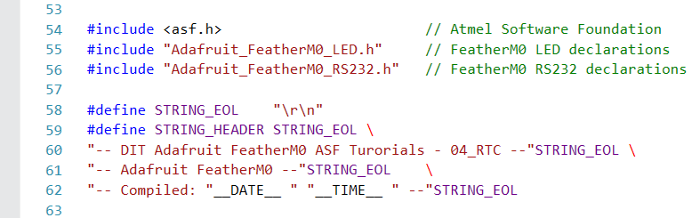
- In line 58 I have defined a symbolic name for the end of line characters of a string.
- Lines 59..62 define the welcome message, the program should print to the terminal at startup.
The compiler replaces__DATE__and__TIME__with the current date and time at compilation time.
Quite convenient, if you have to figure out what version of your software your board is actually running.
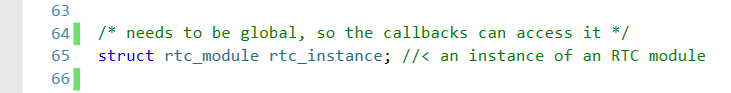
Line 65 creates an instance of an RTC module data structure. This variable needs to be globally accessible throughout this compilation unit, so it can be accessed from within the callback functions.
RTC callbacks
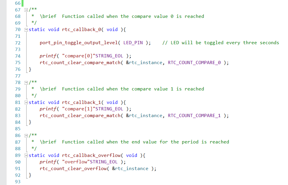
These callback functions are implemented in lines 70..92.
rtc_callback_0(lines 70..76) is called when RTC countercompare_values[0]is reached.
It- Toggles the LED
- Prints a message to the serial terminal
- Clears the compare match flag for
compare_values[0]
rtc_callback_1(lines 81..84) is called when RTC countercompare_values[1]is reached.
It- Prints a message to the serial terminal
- Clears the compare match flag for
compare_values[1]
rtc_callback_overflow(lines 89..92) is called when RTC counter reached the end of the configured period.
It- Prints a message to the serial terminal
- Clears the match flag for overflow
rtc_count_configure()
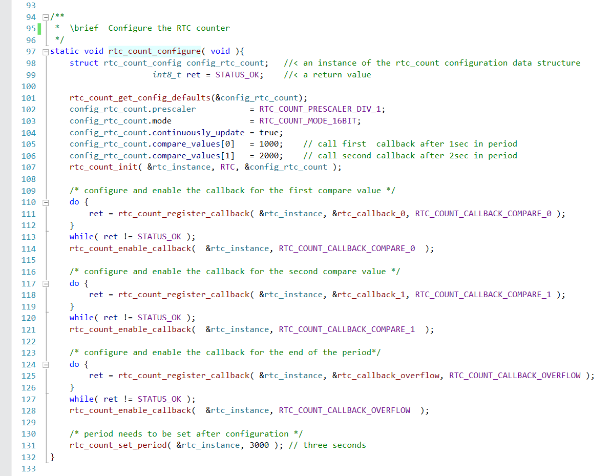
This function configures and initializes the RTC counter and the callback functions.
- A new instance of the rtc_count configuration data structure is created in line 98.
- This instance is initialized with the default values in line 101.
- In lines 102..106 we set the RTC counter configuration for our application
- Line 102 sets the RTC prescaler to divide 1.
The following table shows the RTC frequency depending on the prescaler setting for the Generic Clock Source (inconf_clocks.h) and the RTC prescaler setting.
In this application we use a GCLK Prescaler value of 32 and a RTC Prescaler value of 1. So our RTC counter runs at 1kHz.End-frequency GCLLK Prescaler RTC Prescaler 32kHz 1 1 1kHz 32 1 1Hz 32 1024
- We run the RTC counter in 16bit mode (line 103).
This mode allows us to select the counter period and up to 6 configurable compare values. - We enable continuous counter register updates, so no synchronization is needed for reading (line 104).
- Line 105 sets the first compare value to 1s (1000 at 1kHz). So an event is fired after the first second in each three second period has elapsed.
- Line 106 sets the second compare value to 2s (2000 at 1kHz). So another event is fired after the second second in each three second period has elapsed.
- In line 107 we write the new configuration back to the RTC instance.
- Line 102 sets the RTC prescaler to divide 1.
- The following lines 110..128 try to register and enable the callback functions for the different timer events.
Since there is no point to continue with the application until the callback registration was successful, we run the registration calls in loops.- Line 111 registers our callback function for the event that is fired when the first second in the period has elapsed.
- Line 114 enables the event once the callback function is registered.
- Line 118 registers our callback function for the event that is fired when the second second in the period has elapsed.
- Line 121 enables the event once the callback function is registered.
- Line 125 we register our third callback function that should be called when the period set has elapsed.
- Line 128 enables the event once the callback function is registered.
- The last line in this function sets the RTC period to three seconds (line 131).
I had to put this on the end of the function, since the RTC did not want to start in my experiments otherwise.
main()

The main function in lines 137..175 is pretty strait forward now, since the program logic is already implemented in the RTC configuration and the callback functions.
- We declare a variable to hold the USART module data structure, for the serial communication module we use (line 139)
- In line 145 we initialize the board
- Line 146 enables interrupts globally
If you forget to enable the interrupts the callback functions will not work. - We use the DIT Adafruit Feather Library functions to:
- Configure the FeatherM0 LED pin (
LED_configure(), line 153) - Configure the FeatherM0 RS232 SERCOM (
RS232_configure(), line 156) - Enable the FeatherM0 RS232 SERCOM (
RS232_enable(), line 157)
- Configure the FeatherM0 LED pin (
- In line 159 we print the welcome message
- Line 166 calls the
rtc_count_configure()function, that sets up the RTC counter and the callback functions - Line 167 enables (starts) the RTC counter
- Finally we enter an infinite loop (lines 173..175) that has nothing to do
We do not configure any callback functions for the serial communication, since we are not actually interested in talking to the terminal.