Electronics
Adafruit FeatherM0 ASF Tutorials
The source code for the tutorials can be found on GitHub.
03_Button - Digital Output
The goal of the third project is for the MCU to be notified when the state of a button changes.
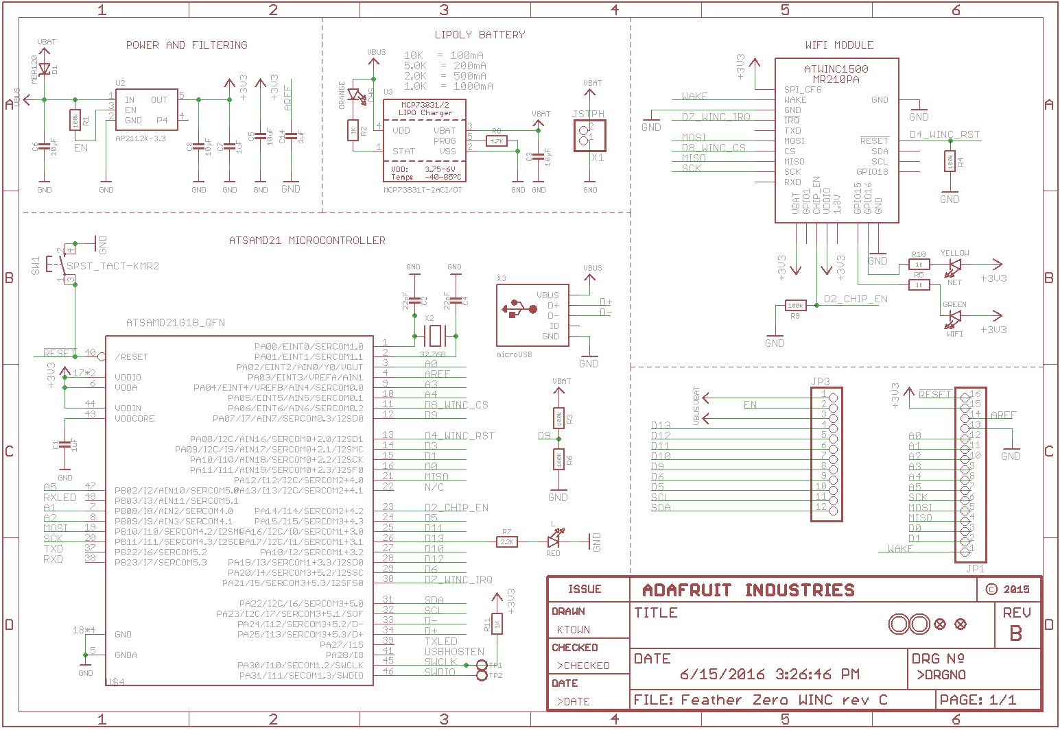 Schematic Source: Adafruit,
License: Attribution-ShareAlike Creative Commons
Schematic Source: Adafruit,
License: Attribution-ShareAlike Creative Commons
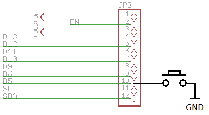
We connect a push-button to JP3.10, which is connected to the MCU's PA15 port (that's pin 24 on an ATSAMD21G18_QFN).
Note:
Usually we would also connect a pull-up resistor of something like 100k between JP3.10 and Vcc to pull the MCU input pin to HIGH
when the button is not pressed.
There is not need for that in this case though, since the ATSAMD21 MCUs have build in pull-up resistors, that can be activated and deactivated by software.
The program will:
- Configure the SERCOM0 module as USART for sending messages to a terminal
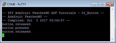
- Print a welcome message to the terminal
- Configure pin
PA15as an digital input pin - Enable the MCU internal pull-up resistor for pin
PA15, so its level is definedHIGH, if the button is not pressed - Attach a callback method to the pin
PA15, that get called if the button is pressed or released and send according messages to a terminal
Adding a new Atmel Software Framework (ASF) Skeleton Project
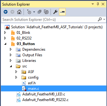
Add a new ASF Skeleton Project for the 03_Button tutorial to the existing solution.
See my Step-By-Step tutorial if you are not sure how to do this.
Choosing a startup project
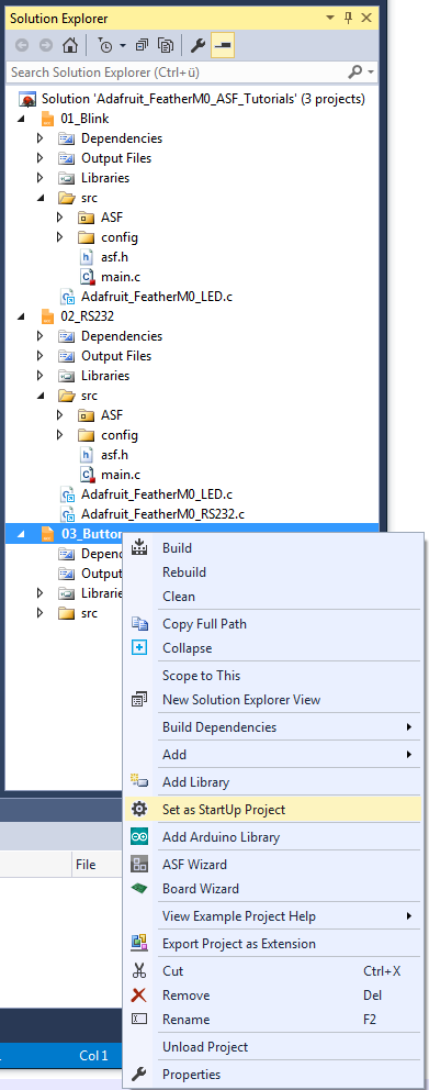
To make sure AtmelStudio always compiles and runs the 03_Button project we make it the StartUp Project.
- In AtmelStudio in the
Solution Explorerwindow right-click on03_Button - In the context menu choose
Set as StartUp Project
Adding the project specific Atmel Software Framework (ASF) code
The next step is to import the ASF modules needed for the specific project.
- Open the ASF wizard under
Project|ASF Wizard - Select Project
03_Button
or use the ASF Wizard entry in 03_Button's context menu.
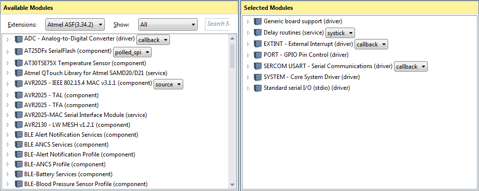
You should see two lists:
Available ModulesSelected Modules
In Selected Modules we already see:
Generic board support (driver)SYSTEM - Core System Driver (driver)
This is the standard framework needed for any ASF application.
In Available Modules find:
Delay routines (service)(systick)
Add>> the module to the project.
This service implements the delay_ms() function.
Now in Available Modules find:
EXINT - External Interrupt (driver)
Add>> the module to the project.
This driver allows us to assign call-back functions to external interrupt events, like the state change of a digital input pin.
Next in Available Modules find:
PORT - GPIO Pin Control (driver)
Add>> the module to the project.
This driver provides easy access to the I/O pins.
Also in Available Modules find:
SERCOM USART - Serial Communication (driver)
Add>> this module to the project.
Which helps us using a SERCOM module in USART mode.
And again in Available Modules find:
Standard serial I/O (stdio) (driver)
Add>> this module to the project.
While this driver is strictly speaking not necessary for the project,
it provides the printf() function for printing to the serial terminal,
making printing messages more convenient.
Now press Apply. This will add all the necessary ASF code to our project.
Using the DIT Adafruit Feather Library
For this project we need to:
- Add the
Adafruit_FeatherM0_LED.hfile path to the include search path of you project - Link the
Adafruit_FeatherM0_LED.cfile to the project - Add the
Adafruit_FeatherM0_RS232.hfile path to the include search path of you project - Link the
Adafruit_FeatherM0_RS232.cfile to the project
See my Step-By-Step tutorial if you are unsure how to do this.
Writing the application code
In the Solution Explorer find the generated main.c.
All we need to import to get the whole ASF magic working is the asf.h, that was generated by the ASF wizard.
The entry should already be there. The wizard took care of that for us (line 53).
- In line 54 we include the
Adafruit_FeatherM0_LED.hlibrary header file. - In line 55 we include the
Adafruit_FeatherM0_RS232.hlibrary header file.
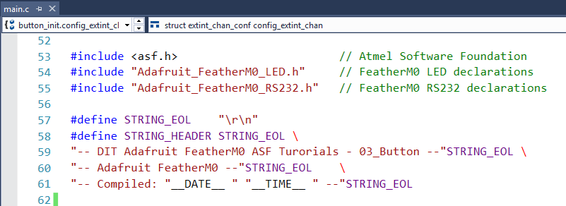
- In line 57 I have defined a symbolic name for the end of line characters of a string.
- Lines 58..61 define the welcome message, the program should print to the terminal at startup.
The compiler replaces__DATE__and__TIME__with the current date and time at compilation time.
Quite convenient, if you have to figure out what version of your software your board is actually running.
I/O pin definitions

The lines 63..65 are specific to the pin we have connected the button to.
These are the values you have to change, if you are using a different pin.
- According to my schematics the button is connected to the MCU pin
PA15.
We could have used the specific values for the pin directly in the configuration function. But it is good practice to define verbose abstract names at the top of the file, assign the specific values to them and only use the abstract names in the rest of the code. First of all, if you have to change the values (e.g. because you later want to move the button to a different pin), it is much easier to find the assignment. And second, by using abstract names you only have to change the value assignment on top,. No need to go through the whole implementation and adjust all the references.
- In line 63 we declare, that the button is connected to the MCU pin
PA15 - In line 64 we declare, that in the MCU digital input pad of port PA15 should be connected to the MCU pin
PA15 - In line 65 we declare, that we want to use the external interrupt channel line 15 for detecting pin status changes
Some of the values are kind of hard to remember, but AtmelStudio will try to help you by making suggestions as soon as you start typing.
The declaration in line 64 is necessary, since modern MCUs have more function than they can provide pins for.
PA15 could also be assigned to one of the lines for SERCOM 3 or 4 (pin multiplexing).
So we have to tell the MCU that it should use the pin for the digital I/O line.
button_on_detect()
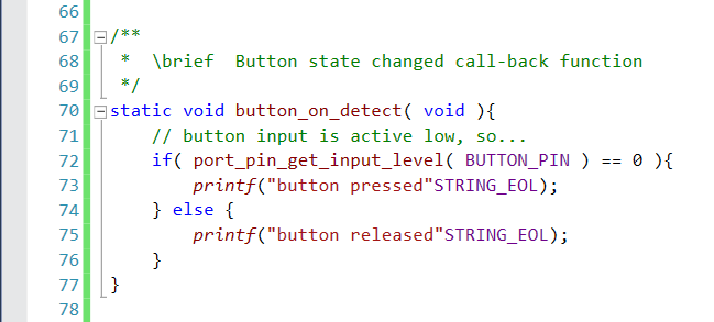
The lines 67..77 implement the callback function that we want the ASF external interrupt channel module to call whenever it detected that the I/O pin PA15 changed status.
Following the schematics, a pressed button connects pin PA15 to ground.
So the pin is active LOW.
We read the current pin state in line 72 and send a message according to the button state to the serial terminal.
button_init()

In lines 82..93 we implement the function that configures the MCU to detect the button state changes.
- Line 83 declares a variable of the external interrupt channel configuration data type
- The variable gets initialized with the default values in line 85
- In line 86 we set the pin we have the button connected to
- We tell the MCU to use the pin as a digital input with the configuration parameter in line 87
- With line 88 we enable the internal pull-up resistor on the pin
- Line 89 tells the MCU to fire an interrupt if the pin status changes from
HIGHtoLOW(button pressed) and also if the pin status changes fromLOWtoHIGH(button released), so the ASF will call our callback function on both events - Line 90 enables the input filter for the pin
This is a best of 3 filter. The MCU takes three measurements of the pin state. The result returned is based on the majority of states detected in these three measurements.
We use this to filter out any bouncing of our switch's contacts. - In line 92 the new configuration is written to the MCU registers
main()

The main function in lines 98..154:
- Declares a variable to hold the USART module data structure, for the serial communication module we use (line 100)
- Declares a variable for return values (line 101)
- In line 107 we initialize the board
- Line 108 enables interrupts globally
If you forget to enable the interrupts the callback functions will not work. - Line 109 initializes the delay service
If you forget this thedelay_ms()functions will not work and the LED will not blink. - We use the DIT Adafruit Feather Library functions to:
- Configure the FeatherM0 LED pin (
LED_configure(), line 116) - Configure the FeatherM0 RS232 SERCOM (
RS232_configure(), line 119) - Enable the FeatherM0 RS232 SERCOM (
RS232_enable(), line 120)
- Configure the FeatherM0 LED pin (
- In line 122 we print the welcome message
- Line 129 calls the
button_init()function, that sets up the external interrupt channel for our button state change detection - In Line 131 we register our
button_on_detect()function as the callback function for button state changes and enable it in line 136. Both functions provide a return value that tells us if the operation (register/enable) was successful. Since there is no point in running the application if they are not, we retry any of them until we are successful. - Finally we enter an infinite loop (lines 145..153) that blinks the LED.
After a reboot this shows us when the MCU is ready for us to press the button and that the MCU can do other things while still detecting correctly when the button is pressed or released.
We do not configure any callback functions for the serial communication, since we are not actually interested in talking to the terminal.