Useful Stuff
From KiCAD to CAD via VRML
Consider using the PCB Module for FreeCAD instead of the VRML method. It is much easier and the results are way better!
Since it is the first one on the list (and I hadn't heard of IDFv3 before), I decided to start with VRML, the Virtual Reality Markup Language export.
For a quick test I plan to:
- create a PCB form a fictional MCU circuit
- export the board via VRML
- find a way to import it into my CAD program
KiCAD (version 4.0.1)
Here the fictional circuit:
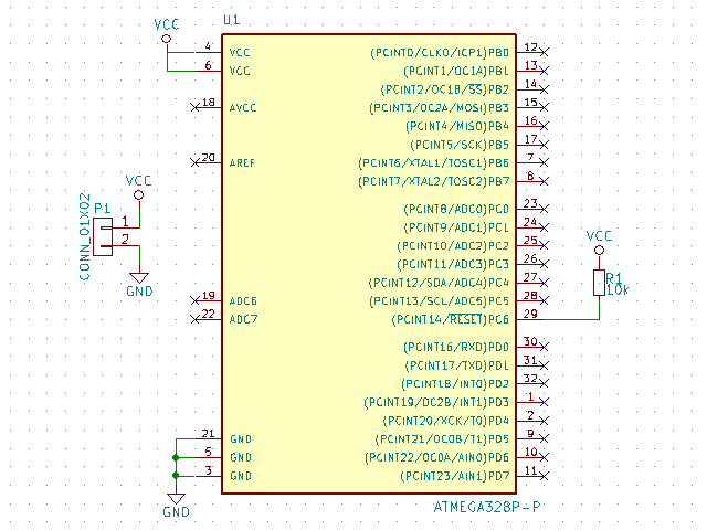
And the PCB:
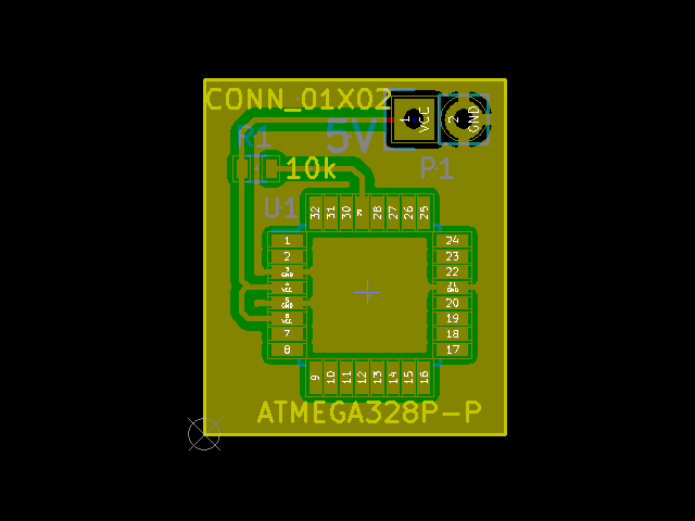
KiCAD's 3D viewer (based on VRML) shows, that all the components are there:
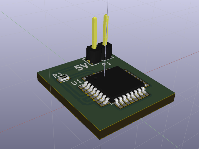
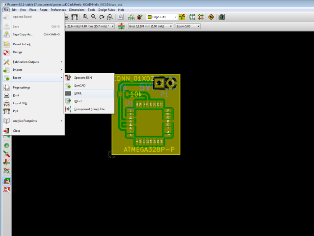
We can export this board using KiCAD's Pcbnew "File|Export|VRML" menu function:
FreeCAD (version 0.15)
Since my own CAD program doesn't speek VRML, I tried FreeCAD and at first the result looks quite promissing:
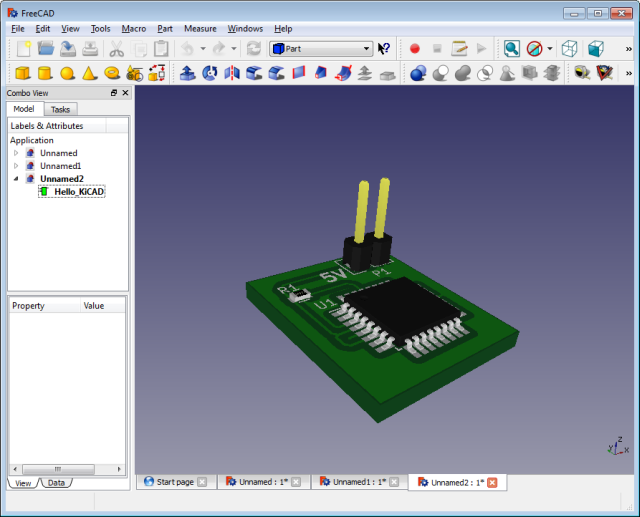
Unfortunately, it seems FreeCAD cannot export a VRML import into a CAD format:
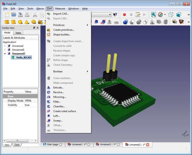
It turns out you need to "Create a shape from the mesh..." first, which (again) it seems you can't do from a VRML import. I'm not sure why that is. Isn't VRML already a mesh format?
Anyway...
The way I went is to use yet another free software MeshLab to convert VRML to STL, before importing the PCB into FreeCAD.
But wait a minute!
FreeCAD is a free and open source CAD program, why not stop here and use it:
- I don't know much about it.
I started to play around with FreeCAD for a while, to see if it could replace my decade old CAD program, but:- While the part design functions appears to be good enough for what I need
- I could not really figure out how to design another part on top of an existing one, creating the perfect fit, as I can do with my old program so nicely.
- It is nice, that FreeCAD can import VRML, but it's still no good.
VRML is a mesh, but what we need for CAD work are shapes. - That is not the assignment!
:-)
FreeCAD seems to be worth spending some extra time with, though.
MeshLab (version 1.3.4 beta)
Trying to import KiCAD's VRML file into MeshLab, I ran into some errors.
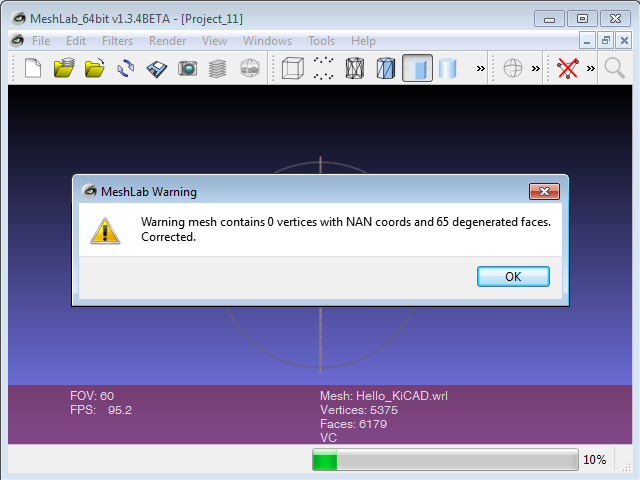
But it says "Corrected." and shows a quite good representation of what I had seen in KiCAD. The colors are a little off. But they are gone in the CAD system anyway. The geometry seems to be fine.
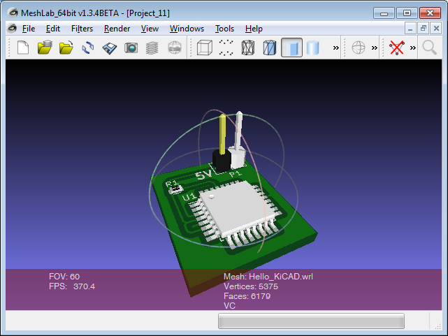
So I didn't worry to much.
But I should have!
While you can use "Export Meash As..." and generate a STL file
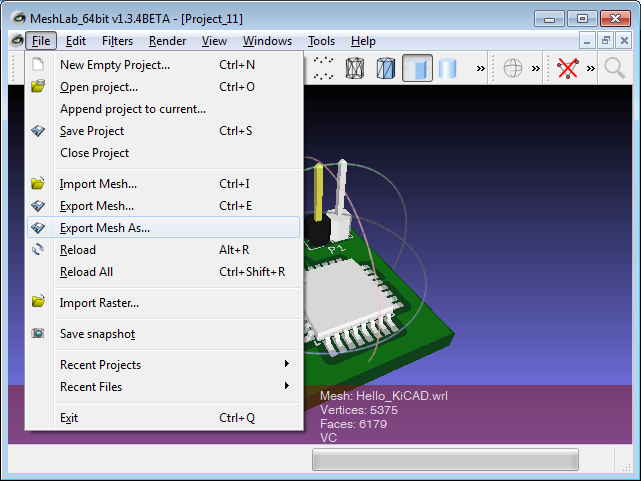
and import that one into FreeCAD.
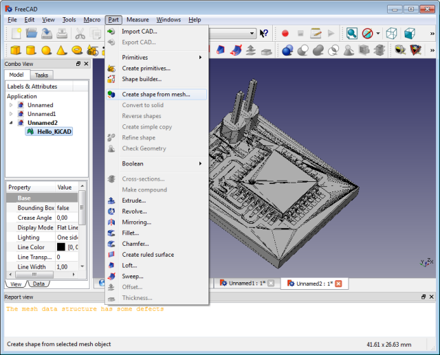
FreeCAD will complain that "The mesh data structure has some defects".
You can ignore the warning and let "Part|Create shape from mesh..." do it's job.
But when I tried FreeCAD's "Part|Export CAD...", no matter what file format (STEP, IGES), the result was always a loose cluster of damaged and missing parts.
So: Fix the mesh problems first!
Fixing mesh problems using netfabb (Basic 7.2.0 423)
Both MeshLab and netfabb seem to be powerfull tools to fix all sort of mesh problems.
I do not have much inside into working with point clouds and meshes just yet (but since I own a LIDAR-Lite 2 now, that will have to change soon :-).
Looking through MeshLab's "Filters" menu, I get the impression that this program is for the expert. It features all sorts of algorithms and you better know what you're doing... or you start reading Meshlab Stuff.
netfabb makes life a little easier. I'm not sure if you still need it, once you are MeshLab-Jedi-Master, but as a (not so :-) young apprentice I found netfabb and it's predefined repair macros very helpful.
In theory netfabb should be able to import a VRML file. But since only in theory there is no difference between theory and reality, that faild when I tried to import the KiCAD exported VRML into netfabb.
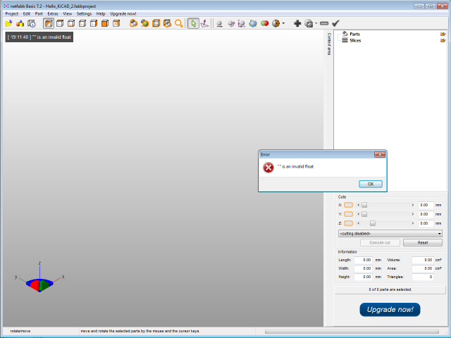
First converting KiCAD's VRML into an STL using MeshLab and importing that STL into netfabb worked.
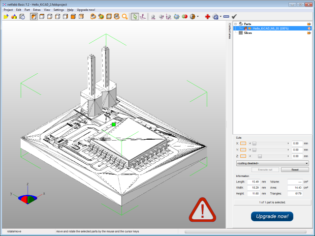
But apperently netfabb is not completely happy with the mesh (as FreeCAD wasn't). Since MeshLab also complained, it looks like maybe KiCAD's VRML export is not completely finished yet. Still good to have it!
Let's see what the "Extras|Repair part" functions can do.
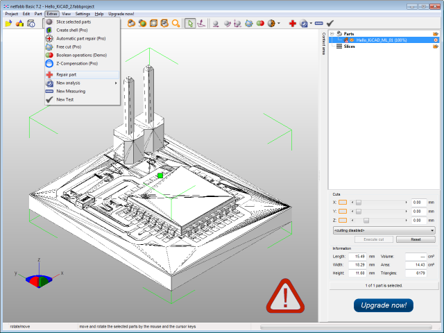
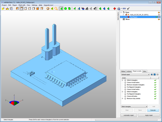
After experimenting for a while, I figured that the following workflow got me the results I wanted:
- goto tab "Repair scripts"
- hit Execute
- hit Apply repair
- hit Remove old part in popup dialog
The mesh looks much cleaner now.
We lost the tracks, but we do not need them for the CAD program. Actually we do want to reduce the amount of information as much as possible anyway, since we do not want to burden the CAD program with information, that has no value during the construction process.
Now we can export the repaired part into a new STL file via it's context menu.
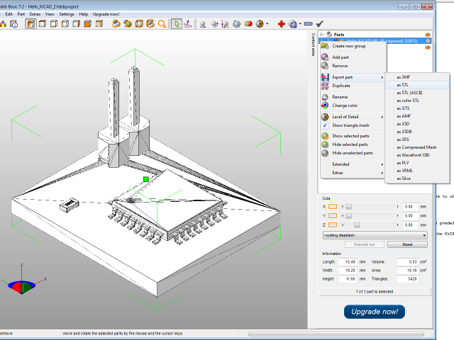
During this process it turns out, that the geometry still has problems:
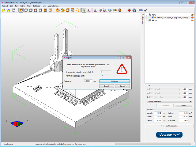
Let's netfabb take care of it, by hitting Optimize.
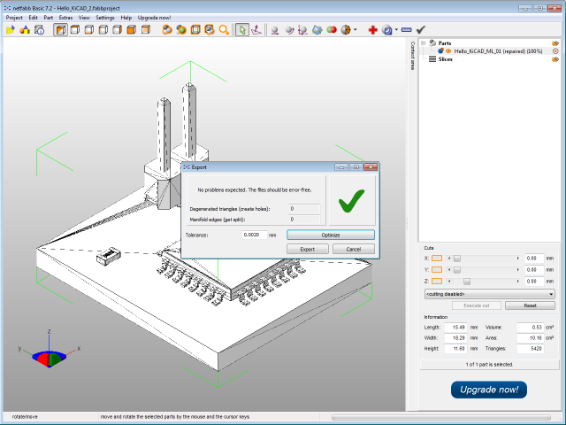
Now that everything seems to be in order, we can hit Export.
Some final houskeeping using MeshLab (again)
Reading On the subtle art of mesh cleaning I found that, especially considering that we do not want to feed the CAD program with to much unneeded, less so wrong information, cleaning up the mesh a bit further sounds like a good idea.
So I reimported the just exported netfabb STL file into MeshLab.
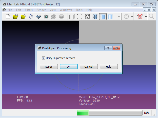
The first task, to remove duplicated vertices, MeshLab offers by itself, right after the import. We accept that, by hitting OK.
Than we let MeshLab remove any unreferenced vertices, by using the according filter
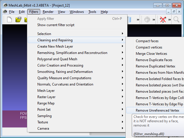
and export the mesh as STL, using "File|Export Mesh As...".
FreeCAD
Now let's see, if the whole effort was worth it.
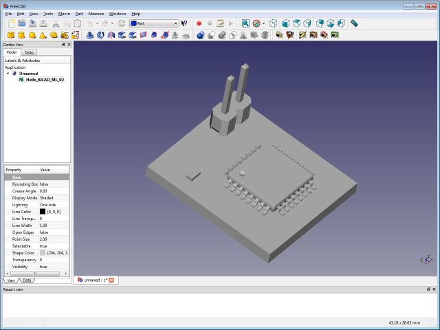
FreeCAD cannot find any errors in the STL file - Excellent!
Using the Part workspace, we:
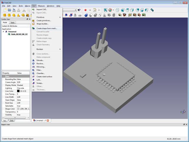
"Create shape from mesh...", with the default tolerance of 0.10 for sewing the mesh together.
Have patience!
Selecting the newly created shape, we can finally use "Part|Export CAD..." to create the desired STEP or IGES file.
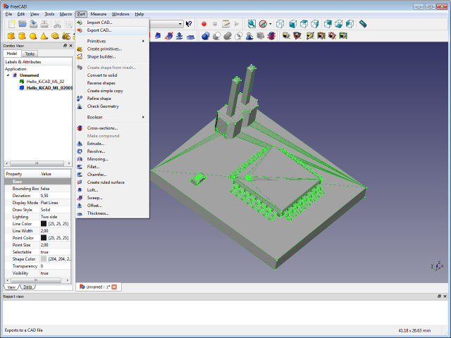
Checking the result
I used the STEP file generated this way and loaded it back into FreeCAD:
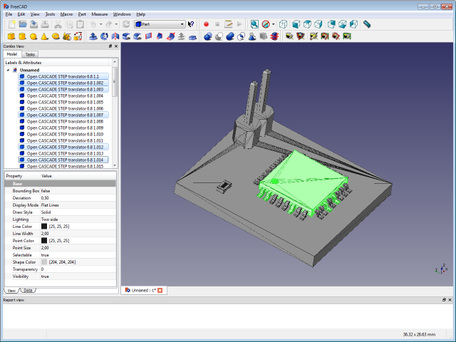
You can see, that FreeCAD now sees the different shapes the board is made of, not only a single mesh anymore. Those shapes can now be selected and worked with like any other shape you would create in a CAD program.
For my second test I used an IGES export and imported it into my old CAD program.
And while trying this before I had tons of error messages and as the result a loose cloud of damaged and missing parts, now I see this:
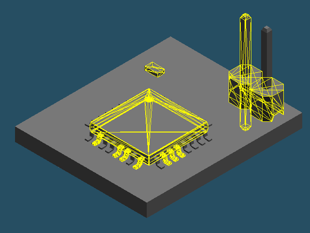
Again, all the diffrent shapes can be selected individually (or as a group) and worked with, as expected from a CAD model.