Prev: 1. Getting good pictures
Useful Stuff
Reverse Engineering of a Keypad in FreeCAD
2. Improving the images
What is a good image depends on what you want to do with it.
We want to:
- outline the keypad
- determine the position and the size of the alignment holes
- outline the size and positions of holes needed for the main keyset and the two function keys in a keyboard cover
- determine the position of the keynobs to be able to position the tactile switches on a pcb correctly
Keypad outlining
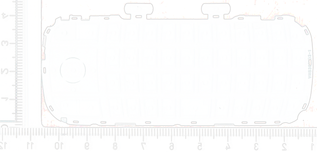
The keys are elevated, so in the front picture the base of the keypad does not sit right on top of the scanner glass. Since this increases the chance for image distortion and other unwanted optical effects, we will use the back side image for outlining the keypad.
For the backside image the keypad is pushed flat down on the scanner glase by the black piece of carton, that also provides a nice contrast.
Using IrfanView's "Image | Effects | Edge Detection" tool, it is not difficult to get a good outline of the keypad and the alignment holes.

Cover breakouts
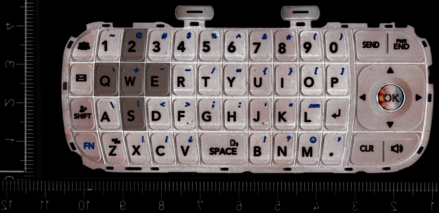
Unfortunately I could not find a setting that would work equally good on the front image, finding the outlines of the Main Button Set or the Function Keys.
So I opted for getting the best view on the outline of those keys by optimizing the image in that direction using "Image | Color corrections..." and inverting the image's colors ("Image | Negaive").

That will most likely also be the way to got, once we try to figure out the position of the keynobs, but I will not go into that in this article.
Next: 3. Outlining