Jolla and SailfishOS
TinkerTOH - The (first) Other Half - Part 1
Today's first order of business: Try to do something with the external hardware connection that makes the Jolla phone so special.
External connections
In The Other Half developer kit we find the pinout of the hardware extension pins.
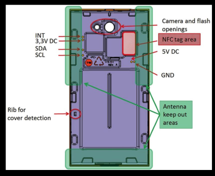 Jolla phone external Connectors
| 3,3V DC | is a voltage output that can be switched on and off by software and used to power TOH (300mA max, 150mA recommended) |
| 5V DC | is a voltage input that can charge the phone (1000mA max) |
| GND | is the common ground (voltage and signals) |
| SDA | I2C bus serial data (1.8V level) |
| SCL | I2C bus serial clock (1.8V level) |
| INT | a GPIO pin that can be used by TOH to trigger an interrupt in the Jolla phone (1.8V level, low active) |
The Jolla phone is always the I2C master and TOH the I2C slave. So the phone initiates all the communication and provides the SCL.
TOH can use INT to signal it's desire to communicate.
As shown by kimmoli here the INT pin can also be used as an output.
First contact
For some initial experimentation I had build an connector PCB that I intended to fit on the back of an extra TOH I bought from Jolla.
Unfortunately that one did not arrive in time and since I did not want to damage the one that came with the phone, I had to use an more tinkerish approach.
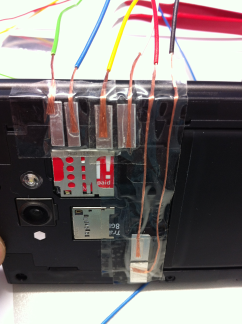
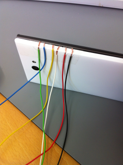
I stripped all the wires of there isolation. This allows them to lay flat, not bulking TOH. The little bulk/gap you see in the right picture comes from a part of the TOH that should snap into the phone. I will have to adjust the wire positions a little to fix that.
Well, the solution is not going to win any beauty contest, but it is quite robust. I carried it from Berlin via Frankfurt(M) to Singapore, in my suitcase and it still works!
Get it up ...
In my experience, if to many things fly around lose on your workbench, you end up using more time fixing connection problems, than actually developing or building something.
"Nothing holds longer than a temporary fix."
Because of that, I decided that I need something better right from the beginning.
It should:
- provide a solid base for experimentation
- be easily assembled and dismantled, so I can take it on the road with me
As the base plate I used a prototype board. This stuff makes quite good construction material.
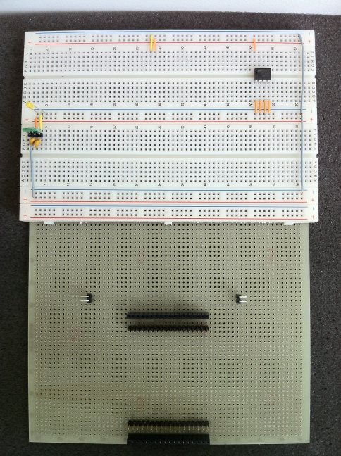
Roughly the top half is dedicated to two bread boards, that glue on very nicely with the tape on the back they came with.
I re-aranged the power bars a little:
- The top bar I dedicated to 5V.
- The middle one to 3.3V.
- The bottom one to 1.8V.
- The last one is spare.
Since we do not need 5V for now and the 3.3V we get form the Jolla phone, there is not much to see here.
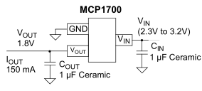
To derive the 1.8V I want to use for the M24C16 I2C EEPROM (you see in the right upper corner), I'm using an MCP1700T-1802E/TT on a 100mil break out board, in a circuit you find in the data sheet.
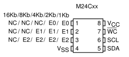
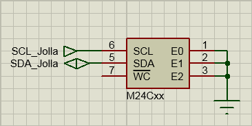
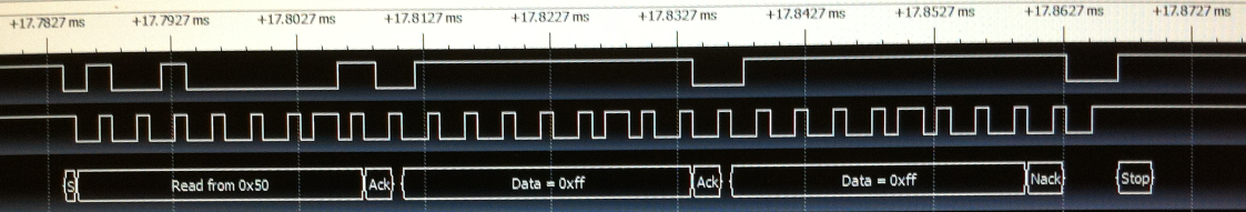
This configuration gives the EEPROM an I2C address of 0x50.
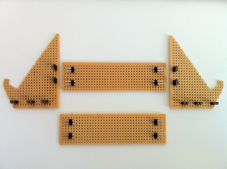
The final mechanical part I needed for now, is a stand for the phone, so it sits tight on the board and is still easy to use.
So again: These prototype boards make good construction materials.
- Cut your parts.
- Solder in some connectors as joints.
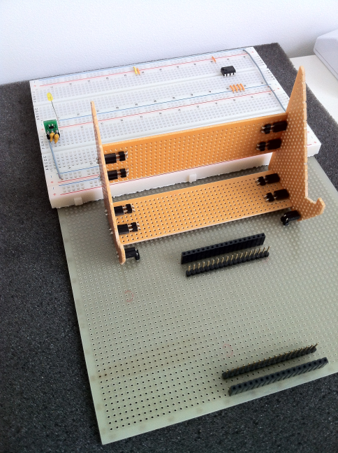
The extra pair of connectors are fixating the stand on the boad. So nothing moves when you are sliding or tapping on the phone.
... and running
After having a nice playground in place, it is time to get something going.
kimmoli has provided us with a very nice tool to test Jolla's external connection called Jolla I2C tool. You can install it from the Jolla Harbour from your phone.
This means: We don't need to start programming Jolla / Sailfish OS before we can test the I2C bus.
Great news! Thank you!
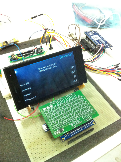
Connecting the EEPROM to the phone and firing up I2C Tool, finds the M24Cxx at 0x50 (as expected) and reads all FF from it (as expected for an unprogrammed chip).
* SUCCESS! *
P.S.: Don't be bothered by the stuff around the phone. The only things needed are:
- The Jolla phone.
- The I2C EEPROM (top middle).
The only interesting thing for this experiment, that you might want to add, is a logic anylizer.
I just got myself LapTool, a decent one for a hobbyist price from Embedded Artists.
Especially if you run into problems, these can give you some valuable information, that saves a lot of time debugging.