Useful Stuff
From KiCAD to CAD using the PCB module for FreeCAD
OK, let's face it: The VRML method is not what I would call convenient. And looking up what people do to work with the IDF export looks even more grim.
Luckily, reading up some more stuff, I stumbled over the FreeCAD-PCB project.
That looks very promissing! Let's give it a shot, using the same sample as in the VRML test.
KiCAD (version 4.0.1)
Here the fictional circuit:
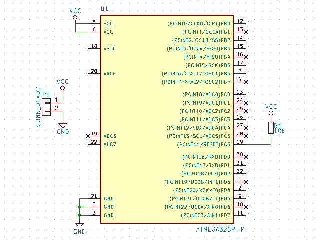
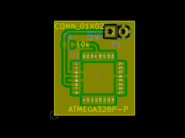
And the PCB:
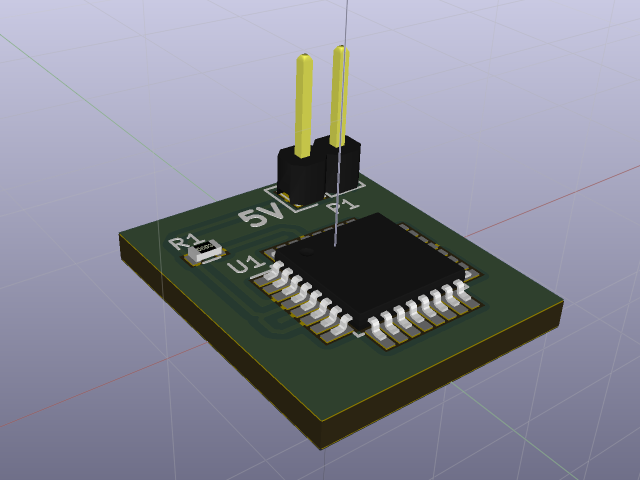
KiCAD's 3D viewer (based on VRML) shows, that all the components are there:
FreeCAD (version 0.15) - PCB Module
Before we start FreeCAD, we download the FreeCAD-PCB module.
As it is with FreeCAD modules, you just unpack the archive and copy it's content into a properly named sub-directory of the ./Mod/ sub-directory of your FreeCAD installation (e.g. C:\Program Files\FreeCAD 0.15\Mod\PCB).
Come on you have to love that! No stupid setup and simple removal, if you tried something and did not like it - Without any residue!
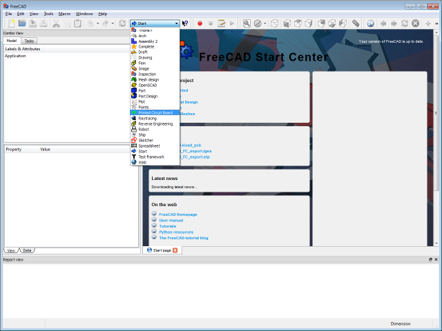
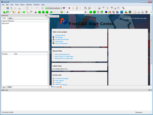
Everything done right, we find a new entry "Printed Circuit Board" in the workbench selection.
If we switch to that workbench we get the new tool bar.
The FreeCAD-PCB module comes without models pre-installed, so we have to download a model library first.
If you do not do this step now, your board will be empty!
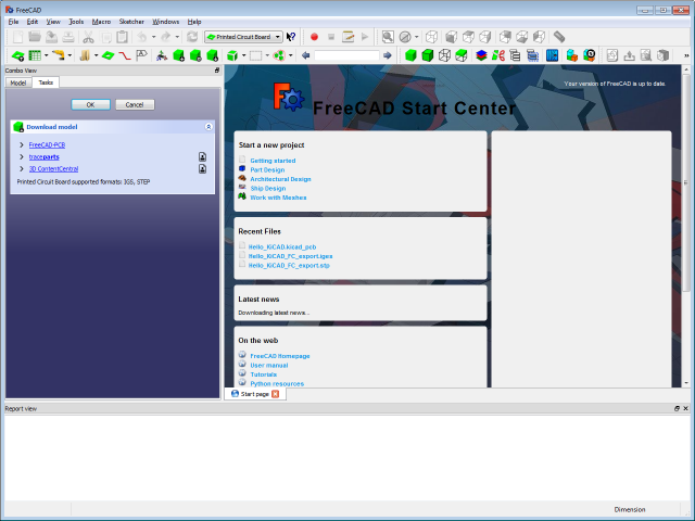
I decided to try the FreeCAD-PCB library first.
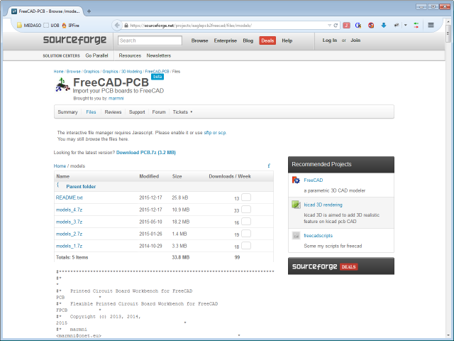
Browsing through the model files I got unsure, if they are supposed to replace or to complement each other. So I opted for unpacking them into the ./Mod/PCB/parts/ directory one over the other, overriding any duplicate files.
FreeCAD (version 0.15) - KiCAD (version 4.0.1) PCB file import
The great advantage of the FreeCAD-PCB module is: It speeks KiCAD (and Eagle, and some other ECAD tongues).
So you don't have to export anything from KiCAD, but open your .kicad_pcb file with FreeCAD!
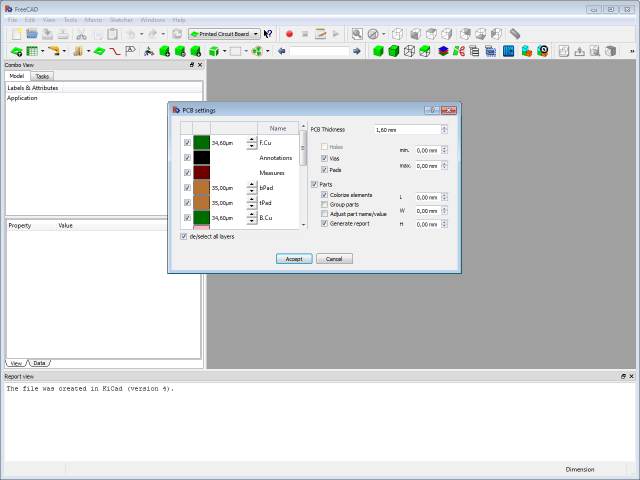
FreeCAD opens the PCB Settings dialog, that allows you to choose the PCB layers you want to import, besides some other stuff.
I selected them all and hit Accept.
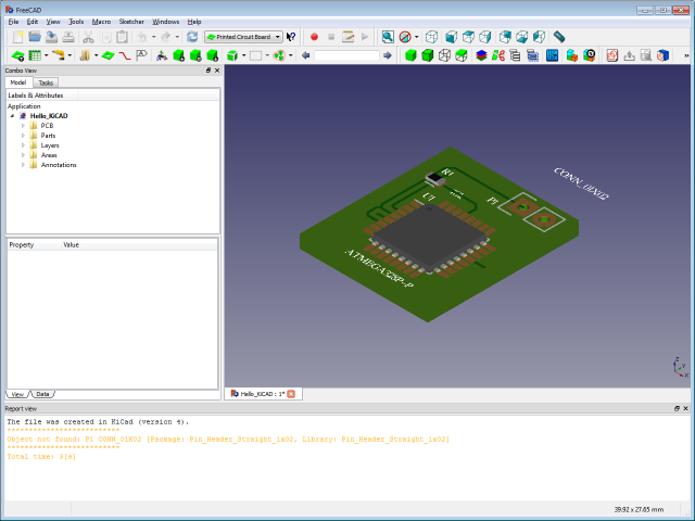
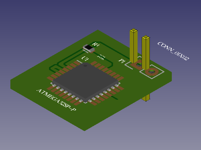
After FreeCAD working for 3 seconds, we have our first result.
Looks quite good already, but the pin header is missing.
During the import FreeCAD complained:
Object not found: P1 CONN_01X02 [Package: Pin_Header_Straight_1x02, Library: Pin_Header_Straight_1x02]
So obviously it cannot assign a model for that part.
Model assignment
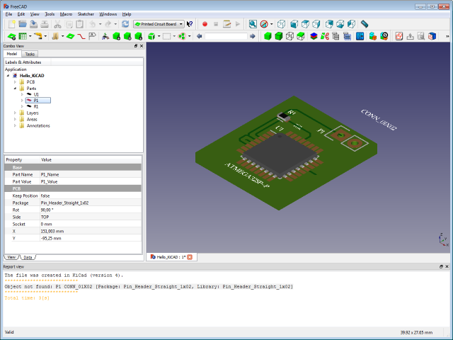
If FreeCAD-PCB cannot assign a model for a part, that part gets a red icon in the Parts branch.
As these headers are such a common part, it is very unlikely that there is no model for them in the library.
FreeCAD-PCB decides what model to use for a part, based on a mapping of model file to Package names.
If you have a very common part and FreeCAD-PCB still does not find a model for it, there is a good chance that the FreeCAD-PCB model just does not recognise the Package name, your PCB program uses.
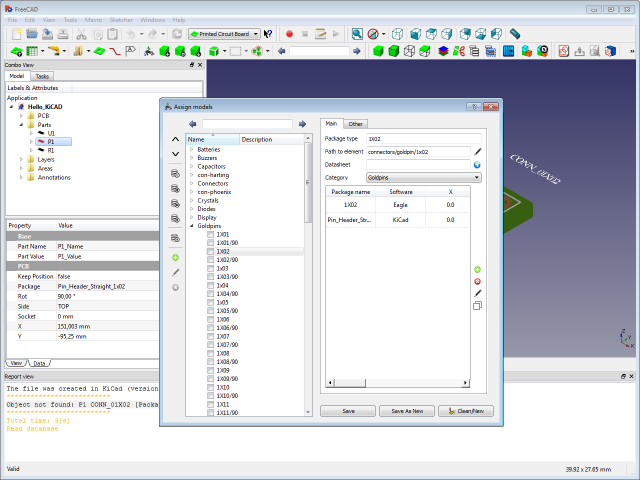
You can fix this by assigning the Package name to a model yourself, using the "PCB model|Assign model" context menu entry of the part in question.

Copy the Package type information from the Assign models dialog. We will need it right away.
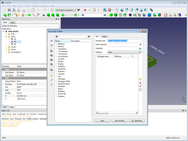
Now, in the still open dialog, try to find a model that fits you package.

For the KiCAD "Pin_Header_Straight_1x02" this should be "Goldpins|1X02".
This model has no entry for the KiCAD "Pin_Header_Straight_1x02" package. We add a new one, using KiCAD's Package name (we just copied) and selecting "KiCAD" as the Software.
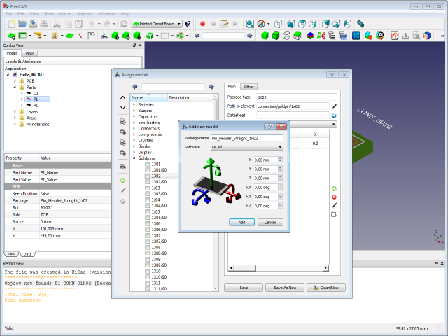
Hitting Add in the Add new model dialog, assigns the KiCAD package name to the FreeCAD-PCB model.
Hit Save in the Assign models dialog and close it to go back to the FreeCAD-PCB workbench.
The update is not immediate.
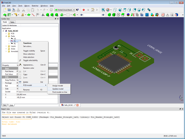
We use "PCB model|Update model" from the part's context menu to propagate the changes made.
Fixing position problems
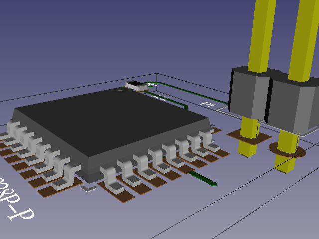
While we now have a model for our pin header part, it appeared in a slightly wrong position.
Taking a closer look, we see, that this is also true for the IC part U1.
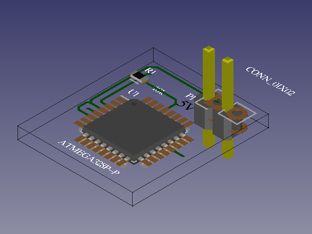
The problem seems to be, that there is no standard on where to put the reference points.
But the developer did take that into account, so the problem is easy to fix.
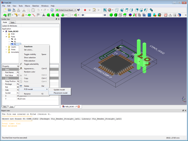
From the context menu of the part, we selcet "PCB model|Placement model".
Make sure you select the correct Library (KiCAD) and start moving the model around
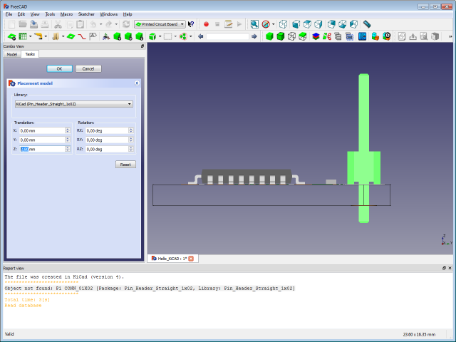
until everything sits nice and square.
The good thing about it is: You only have to do this the first time you assign a new Package name to a model.
FreeCAD-PCB will remember your settings in it's model data base.
CAD export
Since we are already working with shapes, exporting the PCB into another CAD format is merly:
- Selecting all the parts you want in you export (CTRL+A for all)
- Using the "File|Export..." menu (CTRL+E) to write one of the supported file formats.
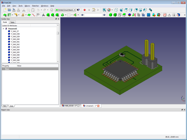
This is what the the reimported STEP file looks like in FreeCAD:
And also the STEP import of my old CAD program is perfectly usable:
