Electronics
LIDAR Lite2 - How to use I2C without Arduino
Part 2 - Cypress CY8C4247LQI-BL483
After some reverse engineering in Part 1 of the LIDAR I2C protocol used in Pulsed Light's demo for the Arduino UNO, lets now see if the new gained knowledge is any good for a different platform.
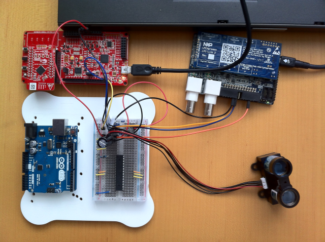
I'm using the Cypress CY8CKIT-042-BLE Poineer Kit, with the CY8C4247LQI-BL483 daughter board mounted.
Since the Pioneer Kit has Arduino UNO compatible headers, re-wirering is just a matter of switching the cables from the Arduino to the Cypress board 1:1.
Protocol testing
To test the protocol independent of any implementation details, I used the Bridge Control Panel Application. This programm is part of the Windows-based PSoC Creater IDE, that Cypress provides free of charge.
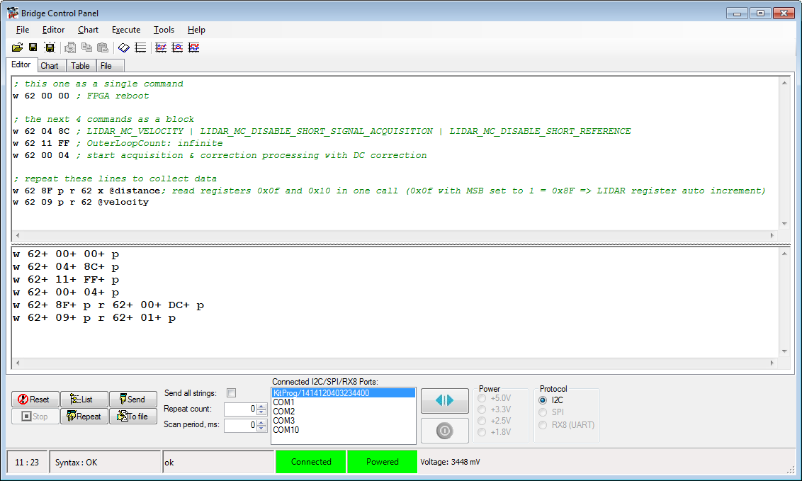
The tool allows us to script sequences of I2C commands.
(You can find the CommandScript.iic in the BridgeControlPanel sub-dir of this project's GitHub repository.)
In the top part of the Editor panel you write the commands.
The bottom part shows the responses.
Readers of Part 1 might recognize some of them.
Putting the cursor in one line of the top part of the Editor panel and clicking the Send button, sends the sequence over the I2C bus.
Selecting multiple lines in the top part of the Editor panel and clicking the Send button, sends all the selected sequences over the I2C bus.
- sequence writes (
w) to the LIDAR I2C address (0x62, first hex value), Command Control Register (0x00, second hex value), the value 0x00 (last hex value), sending the LIDAR theReset
command.
The LIDAR responses to each hex value written with theACKsignal (+) and to the completion of the sequence with theStopsignal (p). - sequence writes (
w) to the LIDAR I2C address (0x62, first hex value), Mode Control Register (0x04, second hex value), the value 0x8C (last hex value).
The LIDAR responses to each hex value written with theBit 7 = 1 Enable velocity measurement Bit 3 = 1 Disable short signal acquisition Bit 2 = 1 Disable short reference ACKsignal (+) and to the completion of the sequence with theStopsignal (p). - sequence writes (
w) to the LIDAR I2C address (0x62, first hex value), Outer Loop Count Register (0x11, second hex value), the value 0xFF (last hex value), configuring the LIDAR for continous measurement mode.
The LIDAR responses to each hex value written with theACKsignal (+) and to the completion of the sequence with theStopsignal (p). - sequence writes (
w) to the LIDAR I2C address (0x62, first hex value), Command Control Register (0x00, second hex value), the value 0x04 (last hex value), starting LIDAR's continous acquisition & correlation processing with DC correction.
The LIDAR responses to each hex value written with theACKsignal (+) and to the completion of the sequence with theStopsignal (p). - The registers 0x0F and 0x10 have to be read to get the two byte distance measurement from the LIDAR.
Using LIDAR's auto increment capability this can be done in one call.Auto Increment is activated by setting the Most Significant Bit (MSB) in the register address.
So, to read the register 0x0F and 0x10 in one call we address the register 0x8F (0x0F with MSB set to 1 = 0x8F => LIDAR register auto increment) .As it is standard for operating the I2C bus:
- The register address to read is written to the LIDAR I2C address (0x62, first hex value)
The LIDAR responses withACK(+) to both bytes sent (0x62 0x8F). - The
Readcommand (r) is send to LIDAR's I2C address (0x62, third hex value), fetching the two bytes from 0x0f (0x00) and 0x10 (0xDC).
(The necessaryRestartsequence between write and read is handled by the software in the background, as is the expectedNACKsignal at the end of the data transfer.)
The LIDAR response with aStop(p) to theNACKsent by the Bridge Control Panel.
- The register address to read is written to the LIDAR I2C address (0x62, first hex value)
Using variables in the Bridge Control Panel
For values to read, you usually put a x in the command sequence at the position of the byte to read.
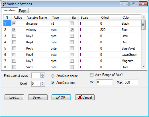
To be able to use advanced features of the program, you can define vatiables using Chart|Variable Settings.
These variables can than be used in the positions where usually the x would be expected.
The VariablesSettings.ini can be found in the BridgeControlPanel sub-dir of this project's GitHub repository.
Using Bridge Control Panel's chart for the LIDAR data
After defining variables we can now use the chart functionality of the Bridge Control Panel application to visualize changes, measured by the LIDAR.
Select the two last lines in the Editor panel:
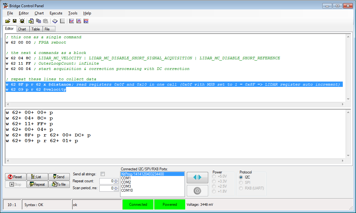
Switch to the Chart panel and click the Repeat button:
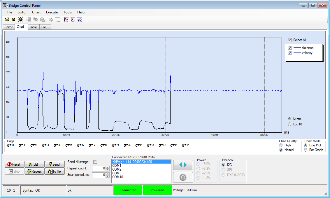
Well, looks like we got the protocol right!
Firmware development
Having the basics in place, we can finally start developing the firmware.
To keep things simple:
- I avoid using advanced features like interrupts for the MCU-LIDAR and MCU-COM communication or the timing
- I will only explain the interesting parts of the firmware
(The complete Firmware project can be found in the GitHub repository.)
The PSoC configuration in the Creator Software is pretty basic:
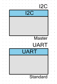
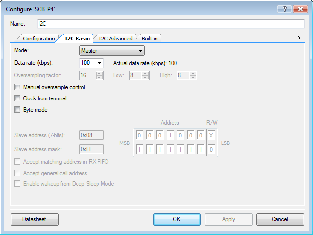
We use an I2C Master for the MCU-LIDAR communication
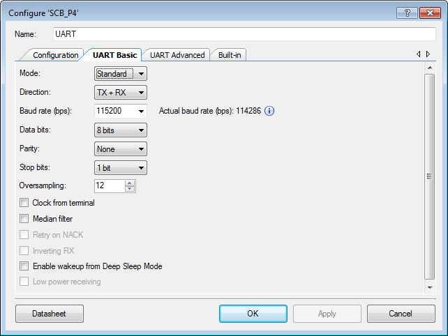
and a standard UART for the MCU-COM communication
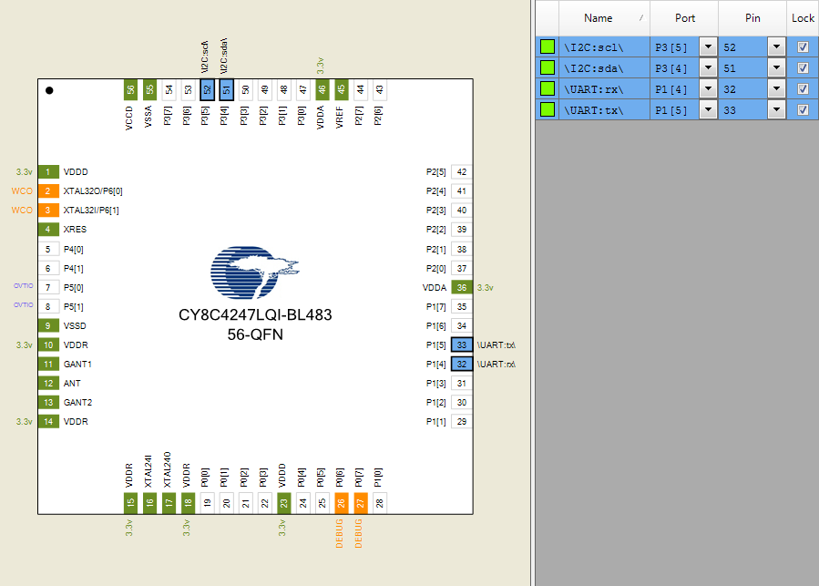
The pin-mapping is dictated by:
- the Kit's USB-COM bridge (UART over USB on P1[4], P1[5])
- Arduino UNO compatible I2C connection (I2C on P3[4], P3[5])
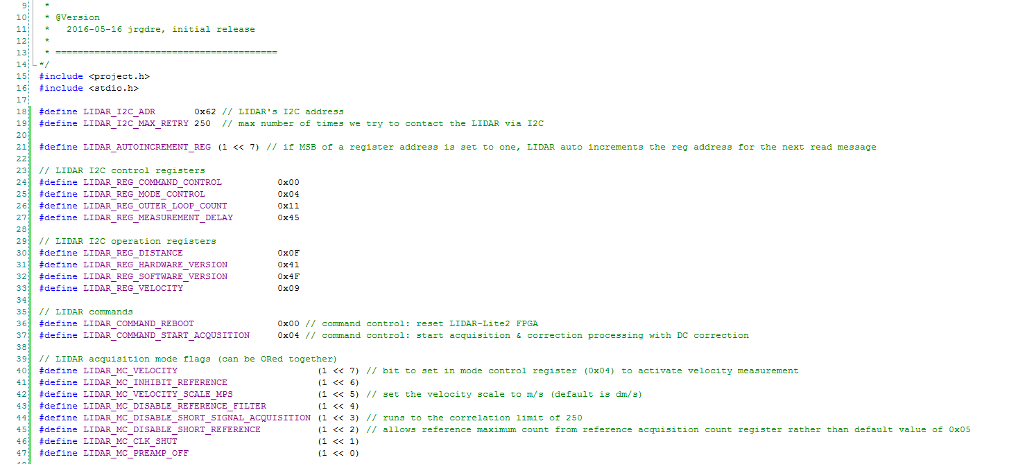
The Firmware source code starts with some definitions to make the code more readable:
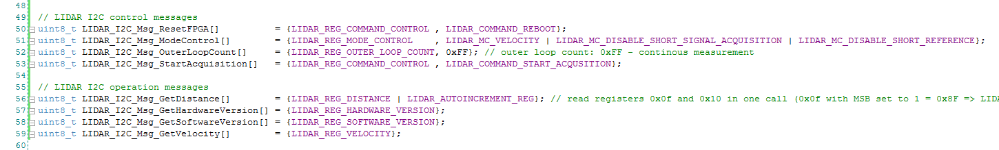
In the next lines we declare the LIDAR I2C messages we are going to send:
The main() function (at the end of the file) controls the whole operation:
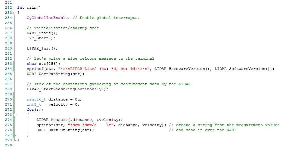
- line 254 enables global interrupts
- line 257 initializes and starts the UART
- line 258 initializes and starts the I2C master
This is pretty much standard code for initializing a PSoC.
At line 260 the custom code starts:
- line 260 calls
LIDAR_Init()to initialize the LIDAR - in line 264 we call
LIDAR_HardwareVersion()andLIDAR_SoftwareVersion()and write the results to a string - line 265 sends that string over the UART using the build in function
UART_UartPutString
(UARTis the name we gave the block_UartPutStringthe generic function name in the UART library)
At this point the initialization is done.
Calling our custom function LIDAR_startMeasuringContinously() put the LIDAR in measuring mode.
We declare a variable for each of the expected measuremnt results and enter an infinite loop.
In that loop we:
- line 274 gets the latest results from the LIDAR by calling our custom
LIDAR_Measure()function - line 275 writes those results to a string
- line 276 sends that string over the UART
Lets now dive a little deeper into some of the custom functions.
LIDAR_Init()
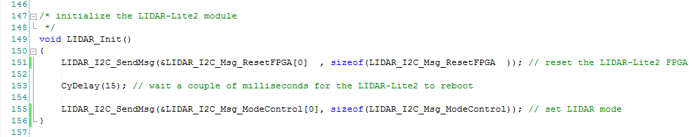
- first sends the
LIDAR_I2C_Msg_ResetFPGAmessage to the LIDAR via I2C, using theLIDAR_I2C_SendMsg()custom function (line 151) - the LIDAR needs a couple of milliseconds to reboot, so we use the build in
CyDelay()function to stall the program for 15ms (line 153) - we finish the initialization by sending the
LIDAR_I2C_Msg_ModeControlto the LIDAR, that sets the right bits in the LIDAR's Mode Control Register
LIDAR_StartMeasuringContinously()
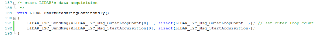
- first sets the Outer Loop Count Register (line 191)
- and than kicks of LIDAR's data acquisition (line 192)
LIDAR_Measure()
Reads the current measurement values form the LIDAR.
It also implements a simple algorithm for averaging over a given number of measured values.
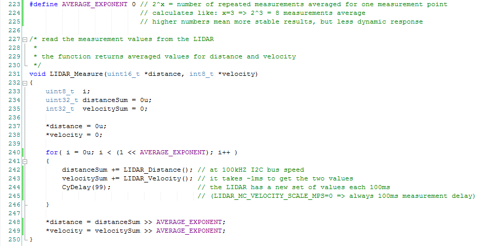
- in line 223 (before the function definition) we define the
AVERAGE_EXPONENT2AVERAGE_EXPONENT is the number of values that get averaged into the value reported back.
Since 20=1, setting theAVERAGE_EXPONENTto0switches off the averaging.Using this exponent system avoids having to use floating point operations. Since every number of values to average is now guaranteed to be a base 2 integer, we can use shift operations in places we would usually have to use divisions (lines 248, 249) or multiplications (line 240), speeding up the processing on platforms that don't have hardware floating point support.
- line 240 starts the averaging loop (..line 246)
- line 242 reads the current distance value from the LIDAR using our custom
LIDAR_Distance()function
and adds it to the sum of distance values for averaging purposes - line 243 reads the current velocity value from the LIDAR using our custom
LIDAR_Velocity()function
and adds it to the sum of velocity values for averaging purposes - Because of the way we configured the LIDAR in
LIDAR_Init(), the LIDAR takes a measurement every 100ms.
Since at 100kbps I2C bus speed it takes only about 1ms to get the two values, we have to waste another 99ms before the next set of values is ready (line 244).
LIDAR_Distance()
Reads the current distance measurement values form the LIDAR.
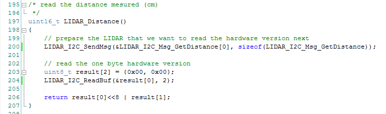
Following I2C protocol
- we first send the address of the register we want to read to the LIDAR, using our
LIDAR_I2C_SendMsg()custom function (line 200)Since the distance is a 16bit value, we actually have the two consecutive 8bit registers 0x0F and 0x10 od the LIDAR.
Using LIDAR's auto increment functionality this can be achieved in one call, adressing the register 0x8F (0x0F with MSB set to 1). - in line 204 we call our custom
LIDAR_I2C_ReadBuf()function to read the two distance bytes from the I2C bus - in line 206 we create a 16bit value from the two bytes and return it to the caller
LIDAR_Velocity()
Reads the current velocity value form the LIDAR.
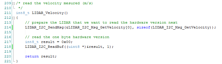
Following I2C protocol
- we first send the address of the register we want to read to the LIDAR, using our
LIDAR_I2C_SendMsg()custom function (line 214) - in line 218 we call our custom
LIDAR_I2C_ReadBuf()function to read the one velocity byte from the I2C bus - in line 220 returns the value to the caller
LIDAR_I2C_SendMsg()
is a helper function, that actually sends a message to the LIDAR via I2C using the build in I2C_I2CMasterWriteBuf() function.
The function also implements some error recover and reporting functionality.
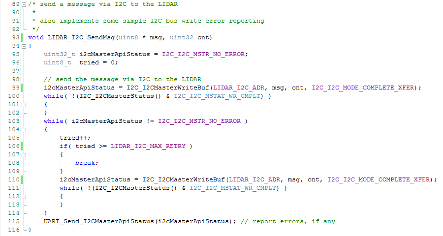
- line 99 tries to send the message to the
LIDAR_I2C_ADR - the loop of lines 100..102 waits for the write to complete
- the next loop (lines 103..114) is run if and for as long as errors are reported by a write operation
- to avoid infinite looping, line 105 increments a counter
- and lines 106..109 brake the loop if this counter reaches the value defined in
LIDAR_I2C_MAX_RETRY - until then in line 110 we re-issue the
I2C_I2CMasterWriteBuf()command - and wait for it to complete (lines 111..113)
- in line 115 we call our custom
UART_Send_I2CMasterApitStatus()function to report the final status of theLIDAR_I2C_SendMsg()function
LIDAR_I2C_ReadBuf()
reads a number of bytes (cnt) from the I2C bus into a buffer (*buf).
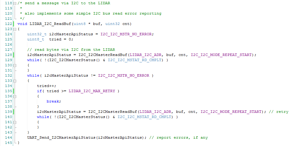
The implementation is equivalent to LIDAR_I2C_SendMsg(),
we just use the build in library function I2C_I2CMasterReadBuf() to read bytes from the I2C bus.
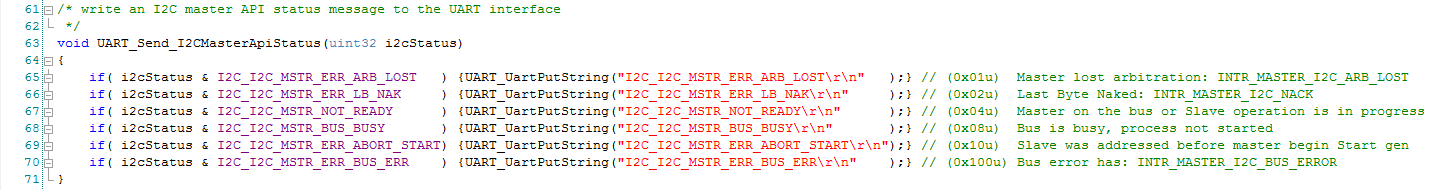
UART_send_I2CMasterApiStatus()
is a helper function, that forwards I2C Master Api Errors as text strings over the UART.
Test run
Now we can
- hook up our terminal emulator (mine is PuTTY) to the virtual COM port of the CY-Kit (for me that is COM10, might be different for you!)
- burn the Firmware into the PSoC's flash
If everything works as it should, you should see a result similar to this
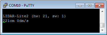
Moving the sensor (or something in front of it) should change the values displayed accordingly.