Electronics
Adafruit FeatherM0 ASF Tutorials
The source code for the tutorials can be found on GitHub.
05_ADC - Analog to Digital Converter
The goal of this project is to get familiar with the Analog-to-Digital Converter of the ATSAMD21.
We will use it to determine the charging state of an attached 2000mAh Lithium Polymer Battery.
 Schematic Source: Adafruit,
License: Attribution-ShareAlike Creative Commons
Schematic Source: Adafruit,
License: Attribution-ShareAlike Creative Commons
Battery Voltage
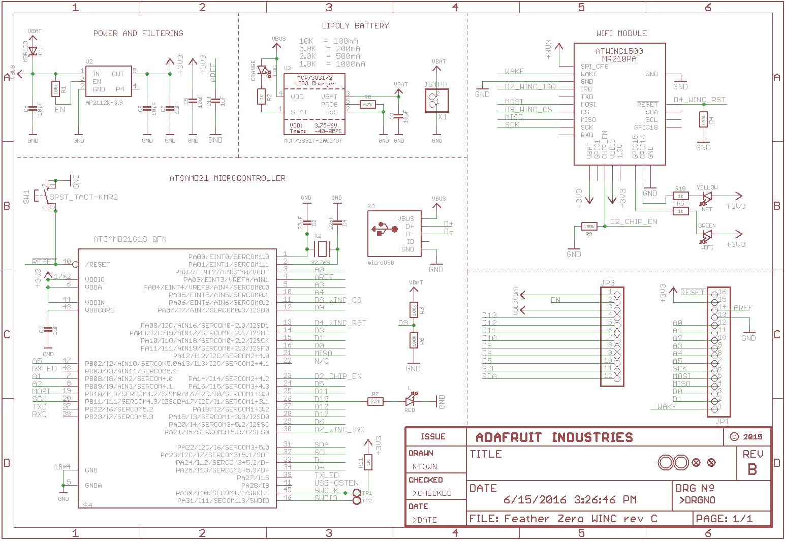
The FeatherM0 has the capability to measure the voltage of an attached Lithium Polymer Battery using the ADC of the MCU on AIN7 (pin PA07).
The Data Sheet of the 2000mAh 3.7V Lithium Polymer Battery I bought from Adafruit states a maximum voltage of 4.2V when fully loaded and a minimum voltage of 3.0V when empty. In the FeatherM0 Manual on page 23 we find the information that the protection circuit shuts down the power at 3.2V.
Since the maximum value to measure can not exceed the reference value and the reference value can not exceed VDDA-0.6V (=2.7V) (SAMD21 data sheet, "36.9.4 Analog-to-Digital (ADC) Characteristics" page 955), the battery value has to be scaled down to meet these limits.
The designers of the FeatherM0 took care of this for us, by using two 100k resistors (R6 and R3) to build a 1/2 voltage divider.
So the value to measure now ranges from 2.1V down to 1.6V.
Reference Voltage
For the ADC to work, it needs a reference voltage, which provides the upper limit for the value to measure.
The SAMD21 MCU provides three internal reference voltages:
ADC_REFERENCE_INT1V
1.0V voltage referenceADC_REFERENCE_INTVCC0
1/1.48 * VCC voltage referenceADC_REFERENCE_INTVCC1
0.5 * VCC voltage reference
And two inputs for the user to provide external reference voltages:
VREFA(pinPA03)VREFB(pinPA04)
The developer has to choose the appropriate reference voltage for his application, taking the limits of the MCU into account:
- 1.0V <= Vref <= VDDA-0.6V
s. data sheet page 995. table 36-21 - 0.0V <= Vin <= Vref
The source code offers the option to use:
- The internal
ADC_REFERENCE_INTVCC0source, by commenting out line 68ADC_USE_EXT_REF_A. - Or to use an external reference value on
VREFA, provided by a circuit like the one below
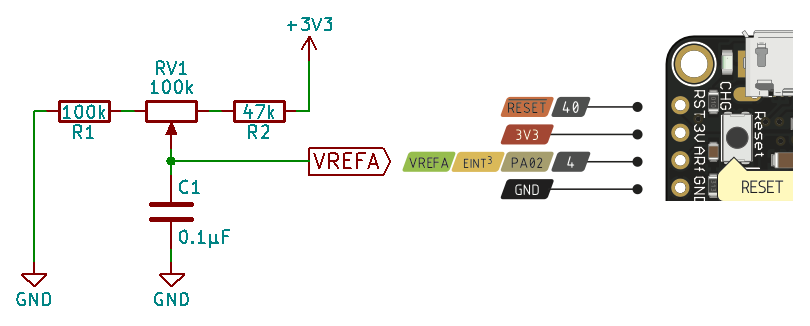
Note:
R1 and R2 are enforcing the limits for Vref.
For the values choosen: 1.34V <= Vref <= 2.67V
C1 helps to stabilize the reference voltage.
Using the internal reference has the advantage of a lower Bill Of Materials count, but:
- The input is limited to 2.23V max. (VCC/1.48V)
- You might miss out on resolution, if the input value is not scaled to the reference value
Using the external reference has the advantage of being able to
- Use the full valid range of Vref up to VDDA-0.6V (=2.7V)
- Scale the reference value to the max. input value, to use the full resolution the ADC provides
Software
The program will:
- Configure the SERCOM0 module as USART for sending messages to a terminal
- Print a welcome message to the terminal
- Configure the Analog-to-Digital Converter (ADC) of the MCU to call a callback function, once it is done reading the analog input
- Print the result of the conversion to the terminal
- Configure the Real Time Clock counter of the MCU to start the ADC at an interval specified
Adding a new Atmel Software Framework (ASF) Skeleton Project
Add a new ASF Skeleton Project for the 05_ADC tutorial to the existing solution.
See my Step-By-Step tutorial if you are not sure how to do this.
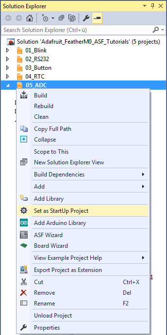
Choosing a startup project
To make sure AtmelStudio always compiles and runs the 05_ADC project we make it the StartUp Project.
- In AtmelStudio in the
Solution Explorerwindow right-click on05_ADC - In the context menu choose
Set as StartUp Project
Adding the project specific Atmel Software Framework (ASF) code
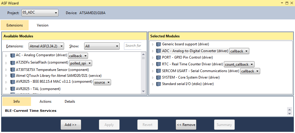
The next step is to import the ASF modules needed for the specific project.
- Open the ASF wizard under
Project|ASF Wizard - Select Project
05_ADC
or use the ASF Wizard entry in 05_ADC's context menu.
You should see two lists:
Available ModulesSelected Modules
In Selected Modules we already see:
Generic board support (driver)SYSTEM - Core System Driver (driver)
This is the standard framework needed for any ASF application.
In Available Modules find:
ADC - Analog-to-Digital Converter (driver) (callback)
Add>> the module to the project.
This driver provides a unified interface for the configuration and management of the ADC module.
Next find in Available Modules :
PORT - GPIO Pin Control (driver)
Add>> the module to the project.
This driver provides easy access to the I/O pins.
Now in Available Modules find:
RTC - Real Time Counter Driver (driver)
Add>> the module to the project.
This driver allows easy usage of the MCU Real Time Clock.
Also in Available Modules find:
SERCOM USART - Serial Communication (driver)
Add>> this module to the project.
Which helps us using a SERCOM module in USART mode.
And again in Available Modules find:
Standard serial I/O (stdio) (driver)
Add>> this module to the project.
While this driver is strictly speaking not necessary for the project,
it provides the printf() function for printing to the serial terminal,
making printing messages more convenient.
Now press Apply. This will add all the necessary ASF code to our project.
Using the DIT Adafruit Feather Library
For this project we need to:
- Add the
Adafruit_FeatherM0_RS232.hfile path to the include search path of you project - Link the
Adafruit_FeatherM0_RS232.cfile to the project
See my Step-By-Step tutorial if you are unsure how to do this.
RTC Clock Setup
The clock system of the ATSAMD21 is very versatile, but it also can be quite confusing to set up for a beginner. There are a couple of moving parts involved. They have to be set up correctly for the RTC to function properly.
We need to set up:
- A System Clock Source (
SYSTEM_CLOCK_SOURCE_XOSC32K)
These are the actual oscillators / crystals that provide the good vibrations.
Since the FatherM0 has especially for real time clock applications a 32.768kHz crystal attached to the MCU we are going to use it. - The Generic Clock Source (GCLK), the RTC is connected to (
GCLK_2).
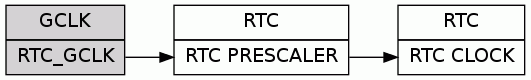
- The connection between the
GCLK_2an theSYSTEM_CLOCK_SOURCE_XOSC32K
In the Solution Explorer find the generated conf_clocks.h.
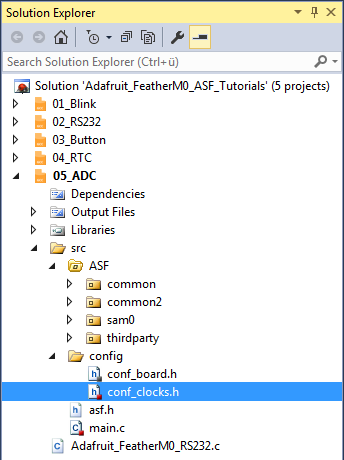
For step 1 find the SYSTEM_CLOCK_SOURCE_XOSC32K section. The following values worked for me:
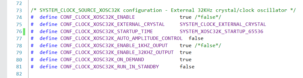
For step 2 and 3 find the SYSTEM_CLOCK_SOURCE_XOSC32K section.
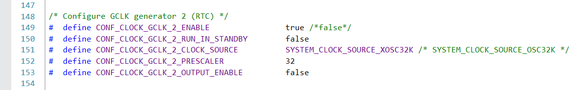
We enable the Real Time Clock generic clock source in line 149 and connect it to the SYSTEM_CLOCK_SOURCE_XOSC32K in line 151.
Writing the application code
In the Solution Explorer find the generated main.c.

All we need to import to get the whole ASF magic working is the asf.h, that was generated by the ASF wizard.
The entry should already be there. The wizard took care of that for us (line 53).
- In line 54 we include the
Adafruit_FeatherM0_RS232.hlibrary header file.
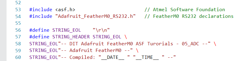
- In line 56 I have defined a symbolic name for the end of line characters of a string.
- Lines 57..60 define the welcome message, the program should print to the terminal at startup.
The compiler replaces__DATE__and__TIME__with the current date and time at compilation time.
Quite convenient, if you have to figure out what version of your software your board is actually running.
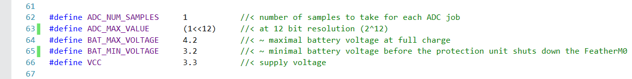
In lines 62..66 we define a couple of symbols that help us to keep the following code a little bit more readable.
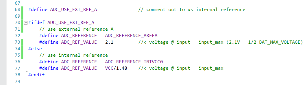
By using or commenting out line 68 we select if the external or the internal reference voltage is used by the program.
If the external reference voltage is used (by using line 68):
- We define the reference voltage to be provided on
VREFA(pinPA03) - The reference voltage value to be 2.1V (set by
RV1).
If the internal reference voltage is used (by commenting out line 68):
- We define the reference voltage to be the internal option VCC0
- The reference voltage value to be VCC/1.48
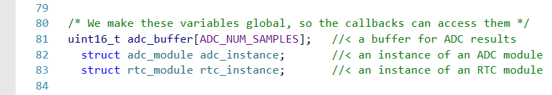
- In line 81 we creates a buffer for the ADC results
- Line 82 creates an instance of an ADC module data structure
- Line 83 an instance of an RTC module data structure
These variables need to be globally accessible throughout this compilation unit, so they can be accessed from within the callback functions.
ADC callback
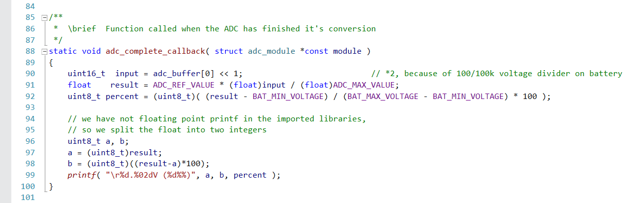
This is the function that gets called once the ADC has finished converting the input.
- Line 90 reads the conversion result from the ADC buffer and multiplies it by 2,
since it was divided by 2 by the
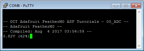
R6/R3voltage divider before. - Line 91 calculates the voltage measured from the conversion result, the reference voltage and the ADC max. value
- Line 92 calculates the battery charging state in percent, from the voltage measured and the battery max. and min. voltages
As the libraries imported for the project do not include a floating point version of the printf() function:
- Line 97 splits of the integer part of the voltage measured from the result
- Line 98 converts the fractional part of the result to an integer
- Line 99 prints the results to the terminal
ADC configuration
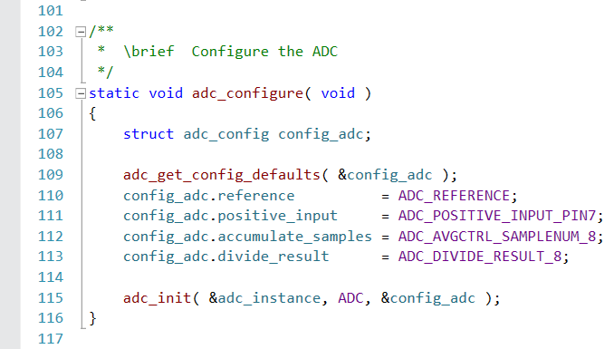
This function configures and initializes the ADC.
- A new instance of the adc configuration data structure is created in line 107.
- This instance is initialized with the default values in line 109.
- In lines 110..113 we set the ADC configuration for our application
- Line 110 sets the ADC reference
The value used depends on ifADC_USE_EXT_REF_Ais defined in line 68 and is either:ADC_REFERENCE_AREFA, the external reference on VREFA (pinPA03), ifADC_USE_EXT_REF_Ais definedADC_REFERENCE_INTVCC0, the internal Vcc/1.48V reference, ifADC_USE_EXT_REF_Ais not defined
- Line 111 configures the input pin for the voltage to measured
The voltage divider for the battery voltage is connected to
AIN07(pinPA07) - In Line 112 we configure the ADC to accumulate eight consecutive measurements
and in line 113 to divide the accumulated result by eight,
returning the average value as the result of the measurement - Line 115 initializes the ADC instance with the new settings
- Line 110 sets the ADC reference
RTC callback
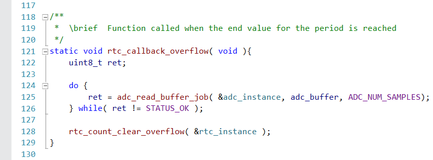
rtc_callback_overflow (lines 121..129) is called when RTC counter reached the end of the configured period.
It
- Starts a new ADC measurement job
- Clears the match flag for overflow
The call to adc_read_buffer_job() is non blocking, but might fail (e.g. if the ADC is still busy).
That is why we embed the call in a loop, that repeats it until the job is accepted.
The ADC measurement job will call the adc_complete_callback(), once it is done.
RTC configuration
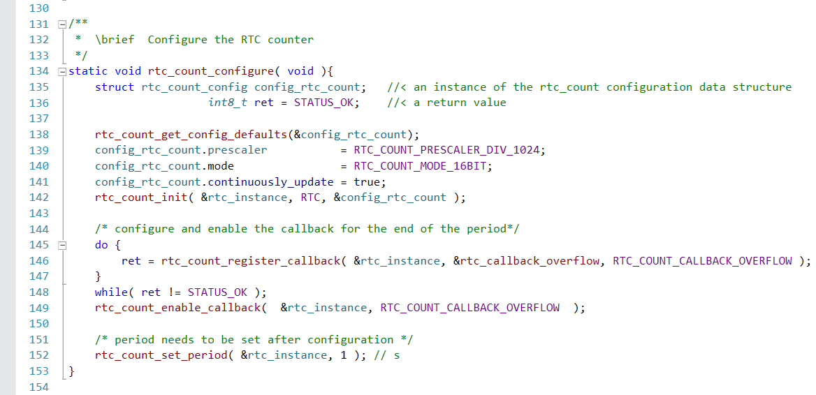
rtc_count_configure (lines 134..153) configures and initializes the RTC counter and the callback functions.
- A new instance of the rtc_count configuration data structure is created in line 135.
- This instance is initialized with the default values in line 138.
- In lines 139..141 we set the RTC counter configuration for our application
- Line 139 sets the RTC prescaler to divide 1024.
The following table shows the RTC frequency depending on the prescaler setting for the Generic Clock Source (inconf_clocks.h) and the RTC prescaler setting.
In this application we use a GCLK Prescaler value of 32 and a RTC Prescaler value of 1024. So our RTC counter runs at 1Hz.End-frequency GCLLK Prescaler RTC Prescaler 32kHz 1 1 1kHz 32 1 1Hz 32 1024
- We run the RTC counter in 16bit mode (line 140).
This mode allows us to select the counter period and up to 6 configurable compare values. - We enable continuous counter register updates, so no synchronization is needed for reading (line 141).
- In line 142 we write the new configuration back to the RTC instance.
- Line 139 sets the RTC prescaler to divide 1024.
- The following lines 145..149 try to register and enable a callback function for the timer overflow event.
Since there is no point to continue with the application until the callback registration was successful, we run the registration calls in loops.- Line 146 tries to register the callback function that should be called when the period set has elapsed.
- Line 149 enables the event once the callback function is registered.
- The last line in this function sets the RTC period to one seconds (line 152).
I had to put this on the end of the function, since the RTC did not want to start in my experiments otherwise.
main()
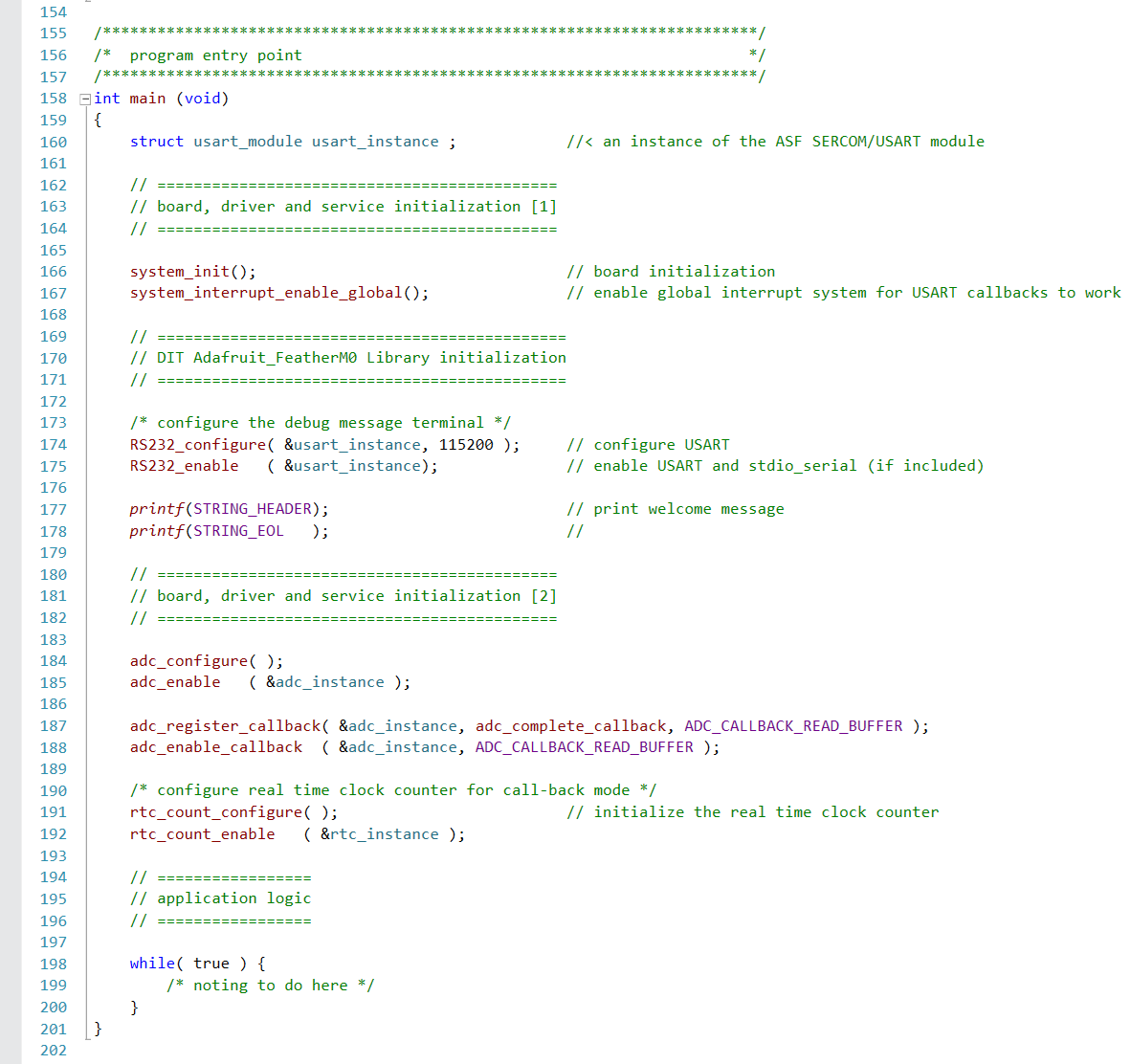
The main function in lines 158..201 is pretty strait forward now, since the program logic is already implemented in the ADC and RTC configuration and the callback functions.
- We declare a variable to hold the USART module data structure, for the serial communication module we use (line 160)
- In line 166 we initialize the board
- Line 167 enables interrupts globally
If you forget to enable the interrupts the callback functions will not work. - We use the DIT Adafruit Feather Library functions to:
- Configure the FeatherM0 RS232 SERCOM (
RS232_configure(), line 174) - Enable the FeatherM0 RS232 SERCOM (
RS232_enable(), line 175)
- Configure the FeatherM0 RS232 SERCOM (
- In line 177 and line 178 we print the welcome message
- Line 184 calls the
adc_configure()function, that sets up the ADC - Line 184 enables the ADC
- Line 187 registers the
adc_complete_callback()function for theADC_CALLBACK_READ_BUFFERevent - Line 188 enables the
ADC_CALLBACK_READ_BUFFERcallback for the event - Line 191 calls the
rtc_count_configure()function, that sets up the RTC counter and the callback functions - Line 192 enables (starts) the RTC counter
- Finally we enter an infinite loop (lines 198..200) that has nothing to do
We do not configure any callback functions for the serial communication, since we are not actually interested in talking to the terminal.